09-13-2024, 02:44 AM
Getting started on my first Philco here, done some research and hopefully I now know enough to be dangerous. 
Overall it's in pretty good shape but it's missing a few things, most notably a speaker and output transformer. If anyone has a speaker and OT that will work (I understand it's the same speaker in a 19, 43 and 71) please let me know!
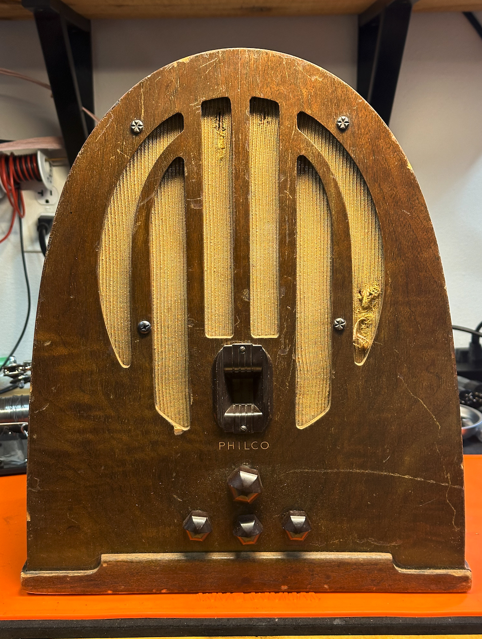
Not a lot of rust, either...
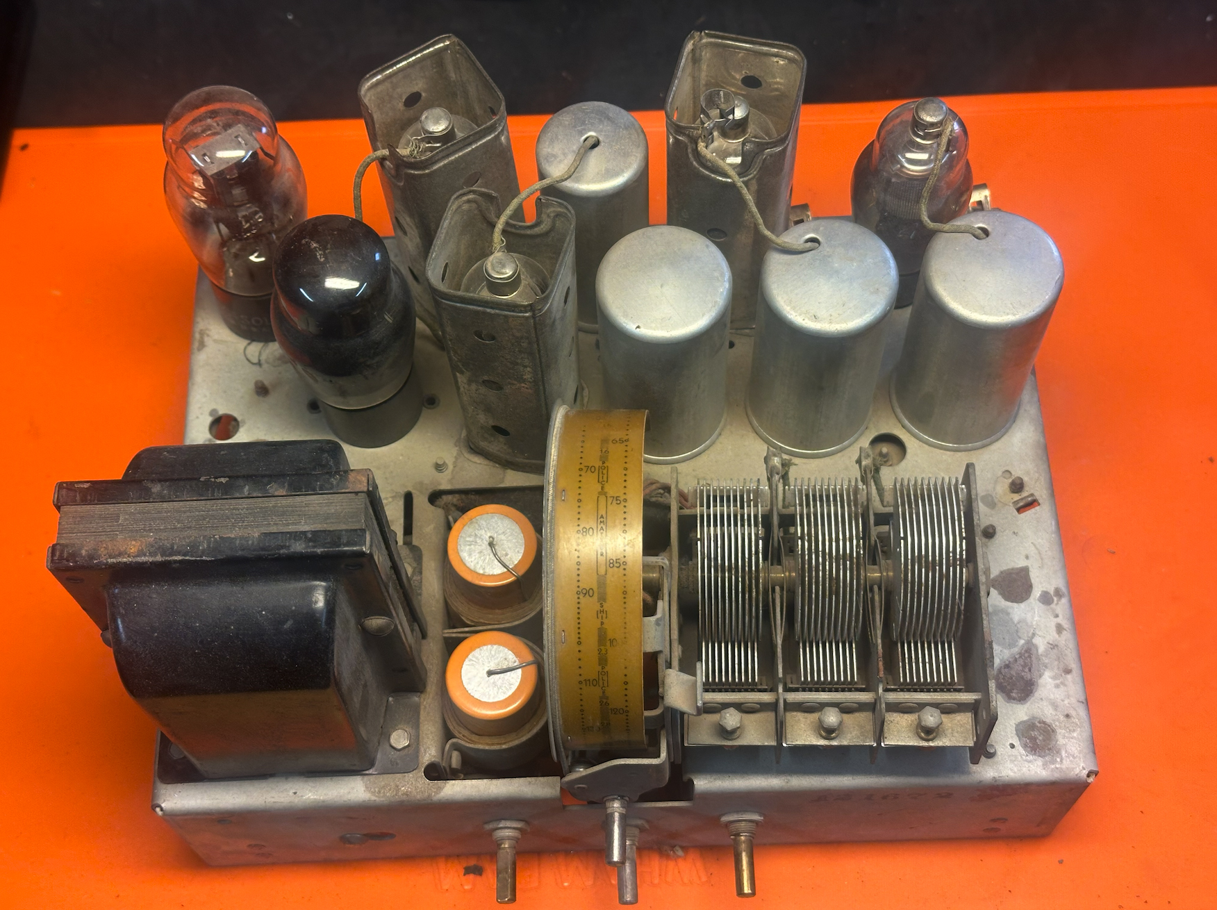
Not too much has changed but there are a couple of whacky things in here...
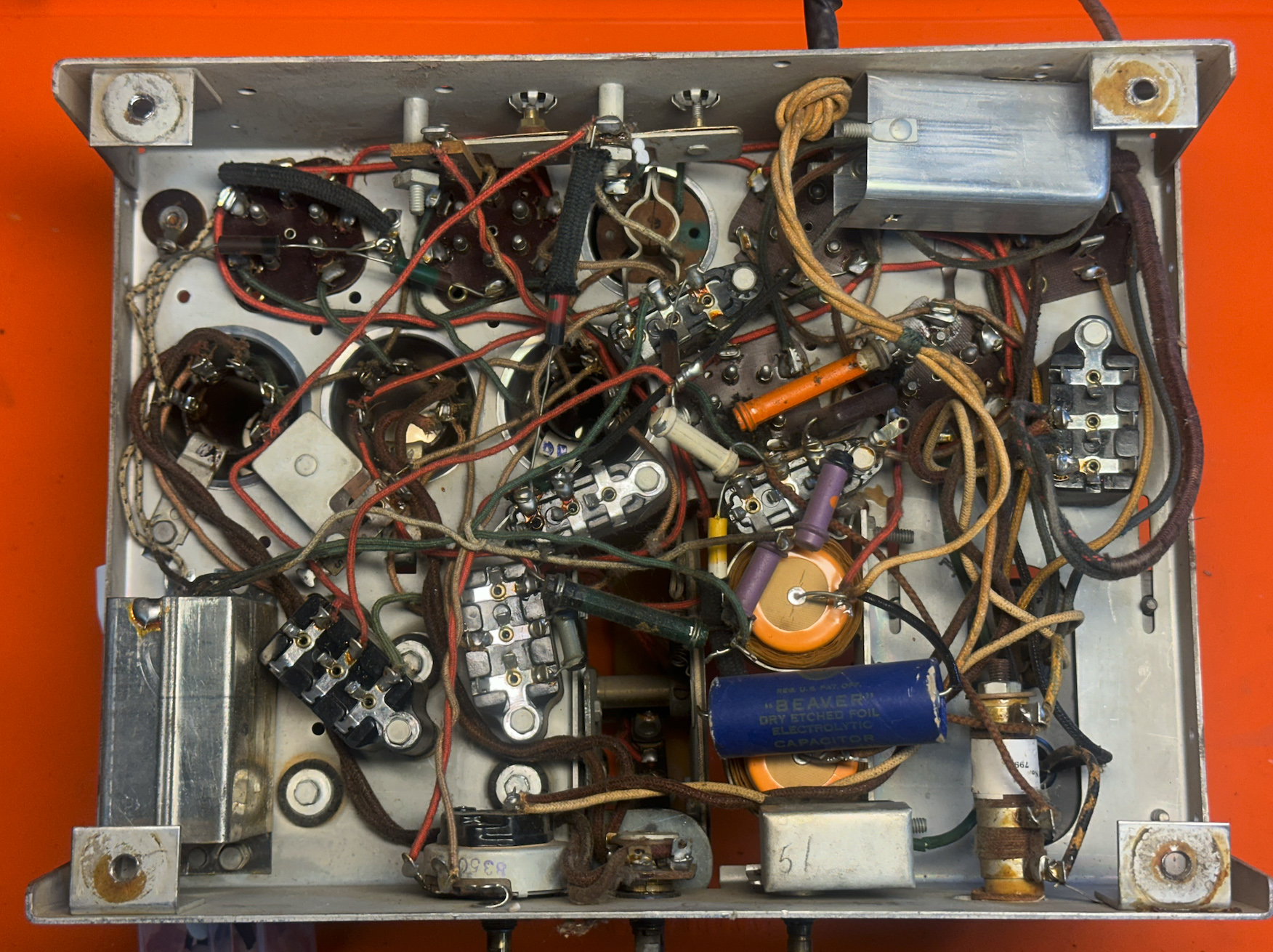
Looks like this cap was just tacked in, not sure if the old one is still in circuit but this is an easy fix...
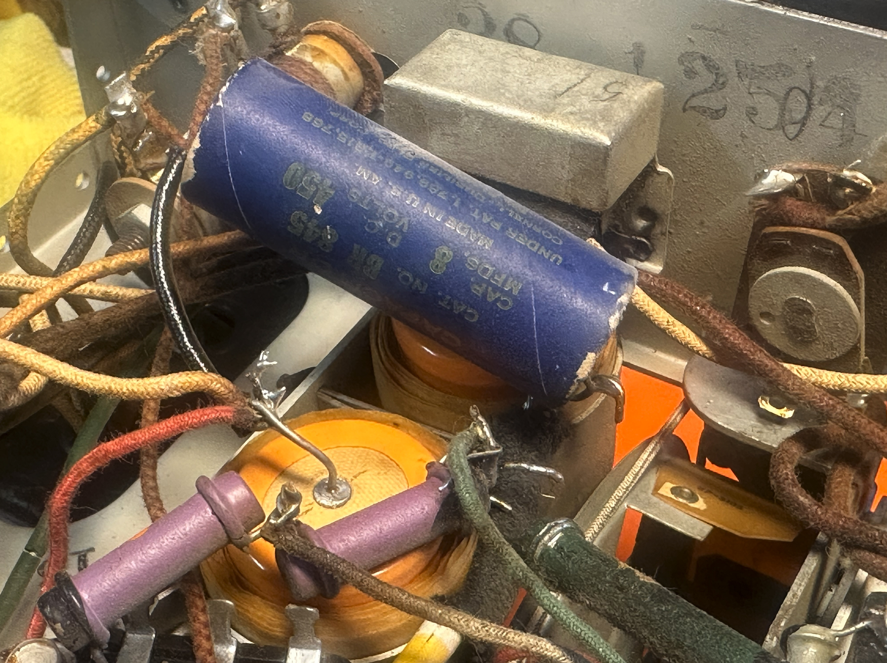
I think this is supposed to be the 2nd IF transformer. Heh, looks like this was pulled from a 40s AA5, definitely doesn't match the other 89s layouts that I've seen online...
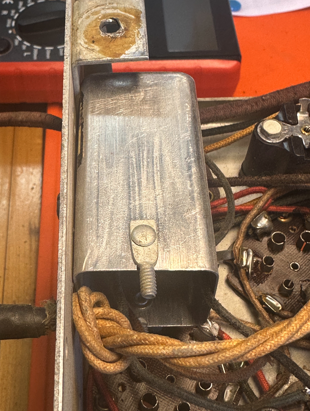
I followed the guide to removing the caps from the tar bakelite boxes and it was incredibly easy! I did 2 in around 20 minutes, way better than some of the horror shows I've seen on youtube. Sure they were the easiest two blocks to get to but I didn't have to unsolder any wires but it looks like these aren't going to be a hurdle after all. Replaced parts 36 and 17...
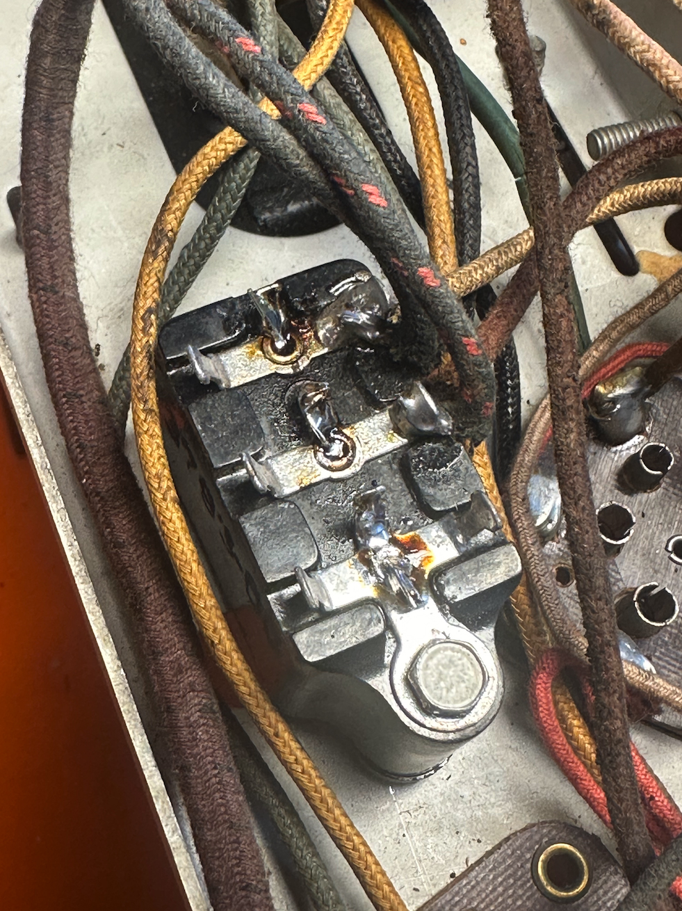
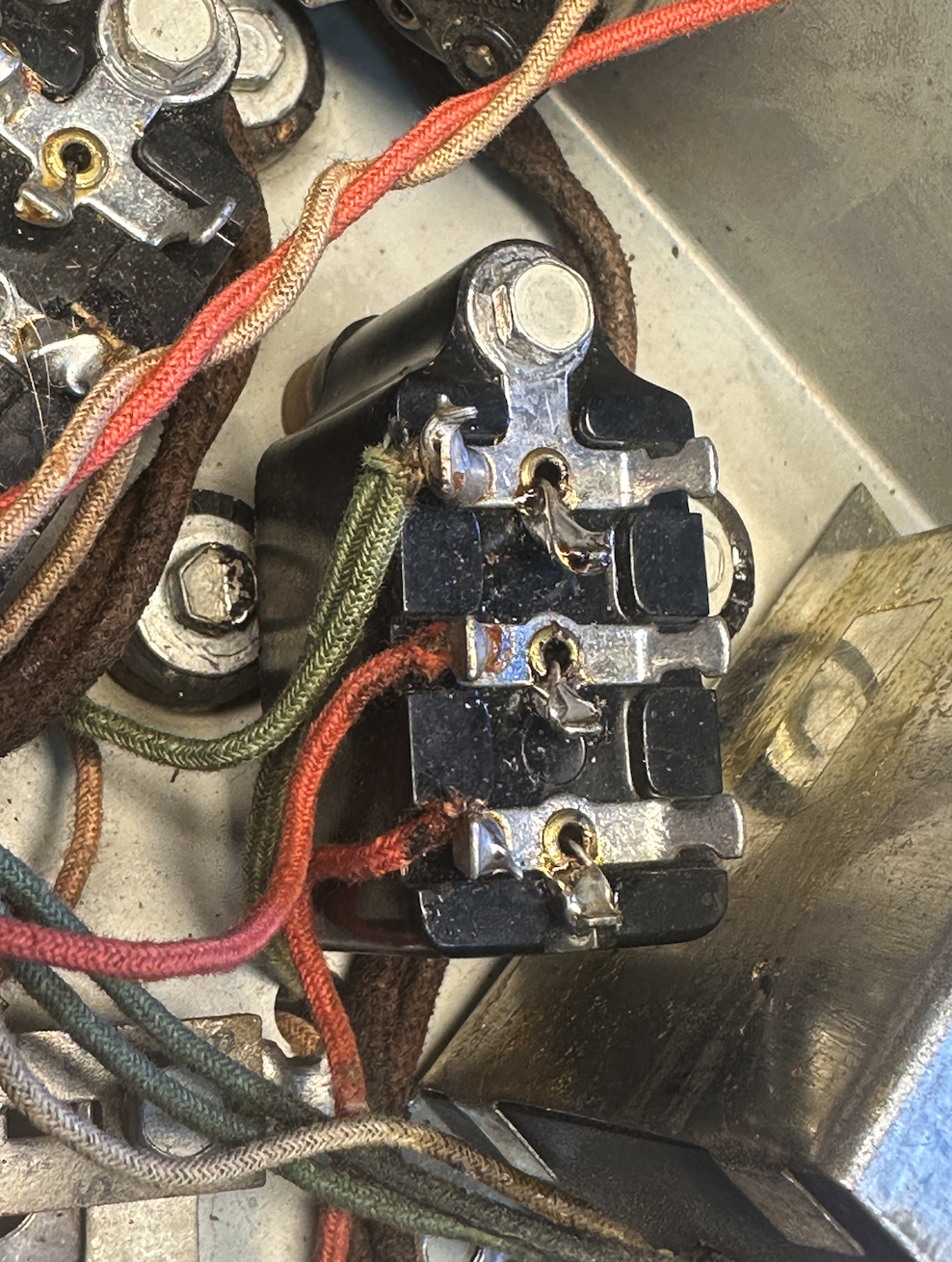
Hopefully I'm on the right track with the other blocks:
Part 23 & 24 are the same value and both go to ground.
Part 26 just has one cap in it, the center is a tie off point.
Part 41 just has one cap in it, the center is a tie off point.
Part 9 is a little less simple with a .0015 and a .05 cap with this strange note: "The .05 mf. section connects the same as condenser 6." Can anyone translate this for me? I see that Part 9 is the .0015 cap in parallel with an 8K resistor to ground so that's pin 2 to 1, should the .0015 cap go from pin 3 to 1? Seems like the only option, are they trying to say that this cap also goes to ground like condenser 6? It's possible I'm overthinking this, just want to be sure.
Part 4 looks pretty simple since the wires are color coded.
The power transformer checks out OK, so does the oscillator coil. Unfortunately the detector/RF coil has an open primary. I've found good instructions on rewinding this coil elsewhere on the phorum so hopefully it'll go smoothly.
I'll probably use 2 watt resistors for the ones that are out of spec. I don't see any ratings on the resistors in the parts list. Resistors 18 and 30 are a little bigger, but maybe that's what 2 watt resistors looked like in the 30s!
I'll look for rubber parts, grill cloth, correct speaker mounting screws and other bits and bobs down the road. Appreciate any insight from people who have tackled one of these before and thanks for this great resource. Glad to be here!
Kurt.
Overall it's in pretty good shape but it's missing a few things, most notably a speaker and output transformer. If anyone has a speaker and OT that will work (I understand it's the same speaker in a 19, 43 and 71) please let me know!
Not a lot of rust, either...
Not too much has changed but there are a couple of whacky things in here...
Looks like this cap was just tacked in, not sure if the old one is still in circuit but this is an easy fix...
I think this is supposed to be the 2nd IF transformer. Heh, looks like this was pulled from a 40s AA5, definitely doesn't match the other 89s layouts that I've seen online...
I followed the guide to removing the caps from the tar bakelite boxes and it was incredibly easy! I did 2 in around 20 minutes, way better than some of the horror shows I've seen on youtube. Sure they were the easiest two blocks to get to but I didn't have to unsolder any wires but it looks like these aren't going to be a hurdle after all. Replaced parts 36 and 17...
Hopefully I'm on the right track with the other blocks:
Part 23 & 24 are the same value and both go to ground.
Part 26 just has one cap in it, the center is a tie off point.
Part 41 just has one cap in it, the center is a tie off point.
Part 9 is a little less simple with a .0015 and a .05 cap with this strange note: "The .05 mf. section connects the same as condenser 6." Can anyone translate this for me? I see that Part 9 is the .0015 cap in parallel with an 8K resistor to ground so that's pin 2 to 1, should the .0015 cap go from pin 3 to 1? Seems like the only option, are they trying to say that this cap also goes to ground like condenser 6? It's possible I'm overthinking this, just want to be sure.
Part 4 looks pretty simple since the wires are color coded.
The power transformer checks out OK, so does the oscillator coil. Unfortunately the detector/RF coil has an open primary. I've found good instructions on rewinding this coil elsewhere on the phorum so hopefully it'll go smoothly.
I'll probably use 2 watt resistors for the ones that are out of spec. I don't see any ratings on the resistors in the parts list. Resistors 18 and 30 are a little bigger, but maybe that's what 2 watt resistors looked like in the 30s!
I'll look for rubber parts, grill cloth, correct speaker mounting screws and other bits and bobs down the road. Appreciate any insight from people who have tackled one of these before and thanks for this great resource. Glad to be here!
Kurt.


![[-] [-]](https://philcoradio.com/phorum/images/bootbb/collapse.png)


