11-26-2024, 06:48 AM
Hi Cap'n Clock,
Unfortunately, I do not have this radio. This is a shame because this should be a good performer. 2A5s are the same as 42s (6F6s) except for filament voltages. at 7 watts audio and an 8" or 10" speaker, this set should have a big sound. I always recommend adding an aux input to radios like these so period music can be played from a computer or MP3 player with better fidelity than through an AM transmitter.
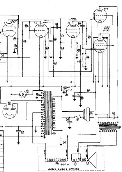
Attached below are sections of the schematic. The first one is the complete audio and power supply section.

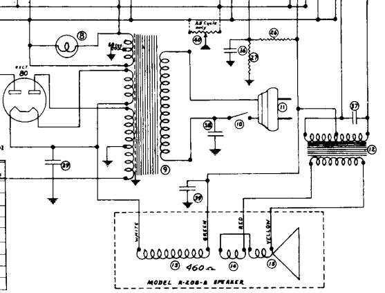
The next is a blow up of the speaker connections.

Examine your radio chassis, topside and underside. Where is the output transformer? Schematics will correctly indicate the radio's circuit but not necessarily the location. From the above section of the Rider's Schematic that I obtained from Nostalgia Air, it appears that the
output transformer should be on the chassis or on the underside of the chassis. You will need to inspect your radio chassis and speaker to locate the output transformer. It does not appear that the transformer is on the speaker based on your picture. The speaker looks like a period-correct speaker but may or may not be the original. Different manufacturers use different field coil impedances. Some put the whole radio B+ load through the field coil. Other do not put the output stage plate load through the field coil. Almost all "electrodynamic" speakers (speakers with an electromagnet instead of a permanent magnet field) have a "hum bucking" coil. this is wound along with the field coil and is wired in series with the voice coil with a polarity that should "buck" or cancel any hum not filtered out by the rest of the power supply design.
.
If the transformer is on the chassis (maybe the underside?), then there should be 4 leads to the speaker. 2 of these leads (white and green) are for the field coil. The other 2 red and yellow) are for the speaker voice coil. Between the rectifier filament (white wire) and the output tube screens (green wire) there should be about 460 Ohms. Between the speaker voice coil (and hum bucking coil in series with it) the resistance should be very low. Because the speaker voice coil / hum bucking coil is in parallel with output transformer secondary, the connection must be disconnected to correctly measure the voice coil.
If 2 of these speaker leads go directly to the output tube plate connections, then your speaker is likely incorrect as only "magnetic" speakers have a direct connection to the output stage without a transformer. In the 1930s, magnetic speakers were used only on battery powered radios.
Hope this helps.
Unfortunately, I do not have this radio. This is a shame because this should be a good performer. 2A5s are the same as 42s (6F6s) except for filament voltages. at 7 watts audio and an 8" or 10" speaker, this set should have a big sound. I always recommend adding an aux input to radios like these so period music can be played from a computer or MP3 player with better fidelity than through an AM transmitter.
Attached below are sections of the schematic. The first one is the complete audio and power supply section.
The next is a blow up of the speaker connections.
Examine your radio chassis, topside and underside. Where is the output transformer? Schematics will correctly indicate the radio's circuit but not necessarily the location. From the above section of the Rider's Schematic that I obtained from Nostalgia Air, it appears that the
output transformer should be on the chassis or on the underside of the chassis. You will need to inspect your radio chassis and speaker to locate the output transformer. It does not appear that the transformer is on the speaker based on your picture. The speaker looks like a period-correct speaker but may or may not be the original. Different manufacturers use different field coil impedances. Some put the whole radio B+ load through the field coil. Other do not put the output stage plate load through the field coil. Almost all "electrodynamic" speakers (speakers with an electromagnet instead of a permanent magnet field) have a "hum bucking" coil. this is wound along with the field coil and is wired in series with the voice coil with a polarity that should "buck" or cancel any hum not filtered out by the rest of the power supply design.
.
If the transformer is on the chassis (maybe the underside?), then there should be 4 leads to the speaker. 2 of these leads (white and green) are for the field coil. The other 2 red and yellow) are for the speaker voice coil. Between the rectifier filament (white wire) and the output tube screens (green wire) there should be about 460 Ohms. Between the speaker voice coil (and hum bucking coil in series with it) the resistance should be very low. Because the speaker voice coil / hum bucking coil is in parallel with output transformer secondary, the connection must be disconnected to correctly measure the voice coil.
If 2 of these speaker leads go directly to the output tube plate connections, then your speaker is likely incorrect as only "magnetic" speakers have a direct connection to the output stage without a transformer. In the 1930s, magnetic speakers were used only on battery powered radios.
Hope this helps.
"Do Justly, love Mercy and walk humbly with your God"- Micah 6:8
"Let us begin to do good"- St. Francis
Best Regards,
MrFixr55


![[-] [-]](https://philcoradio.com/phorum/images/bootbb/collapse.png)


