12-24-2024, 04:12 PM
Yesterday I rebuilt the electrolytic caps, and installed it today.
Had to go to Lowes and by a plastic 1" pipe to help hold the caps together when glued. It is 7' long and will probably last me 'till the rest of my life, as it takes under an inch for it to be used in this application.
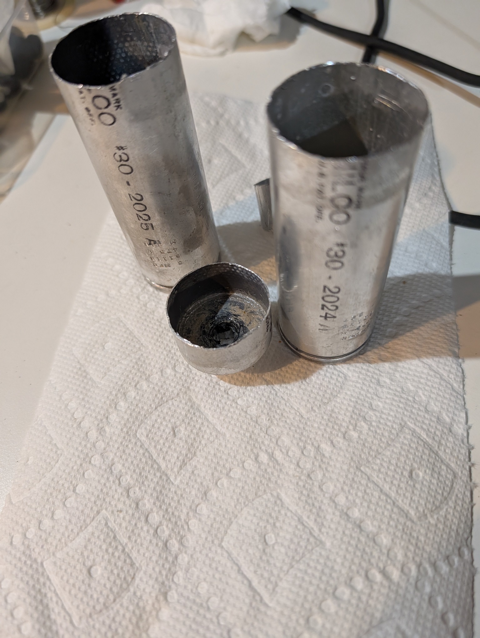
Cut and opened the caps, cleaned out the guts and the plastic mesh, and soaked in vinegar.
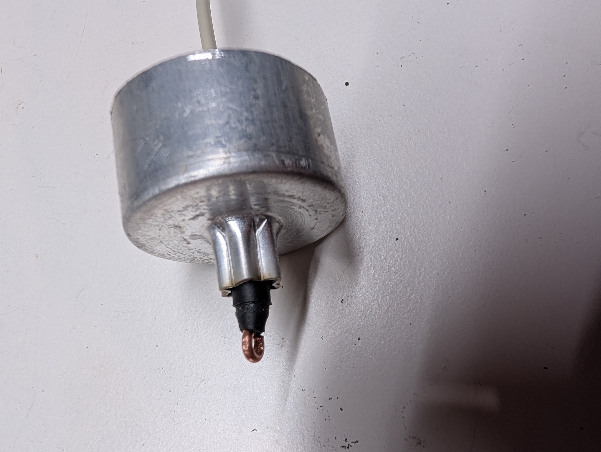
For the center contact I use thick Romex copper wire.
To make it sit well in the center, I put 4 layers of two different adhesive heat shrinkable tubing.
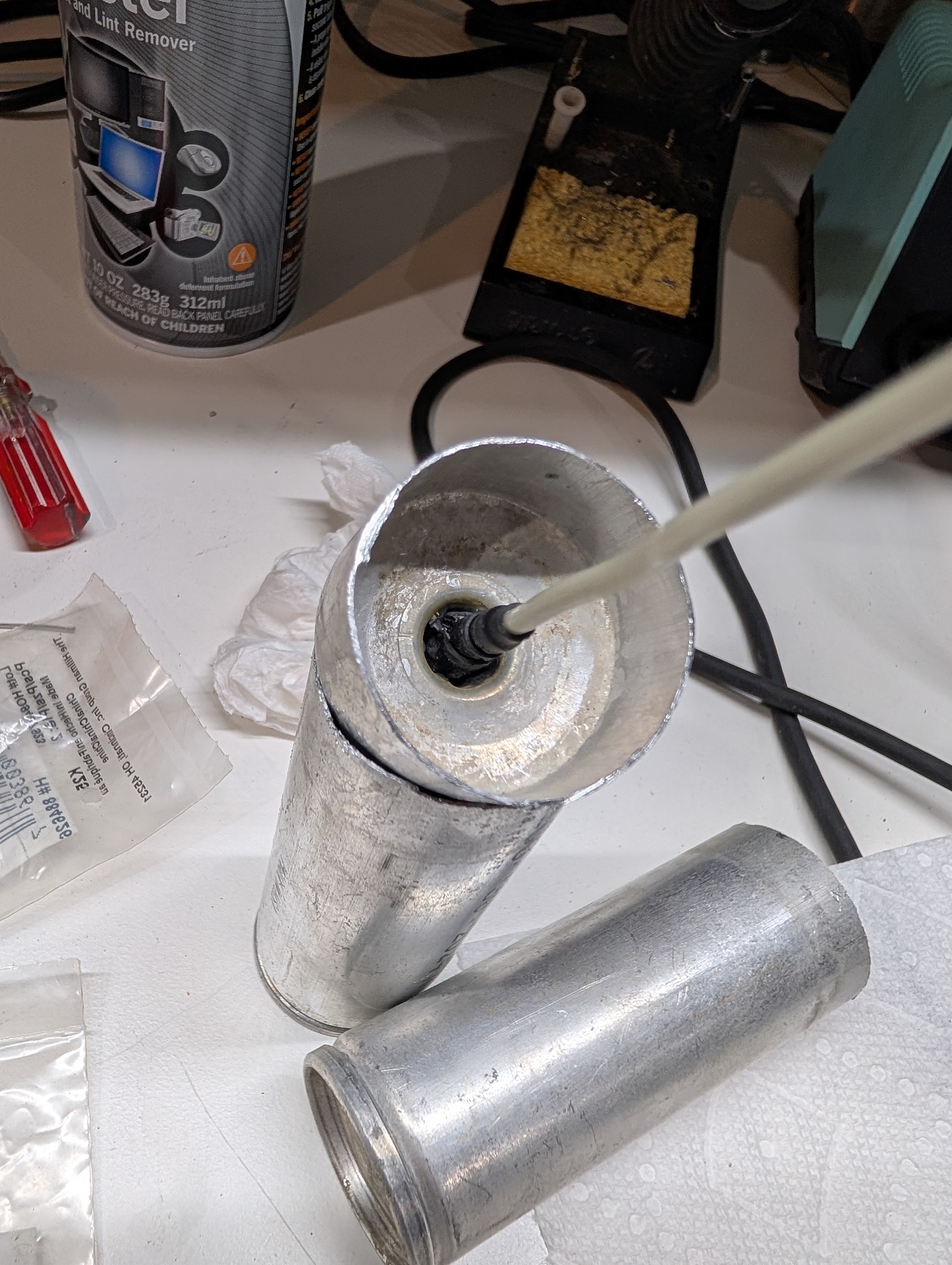
Then I pot it from inside with hot glue, to immobilize.
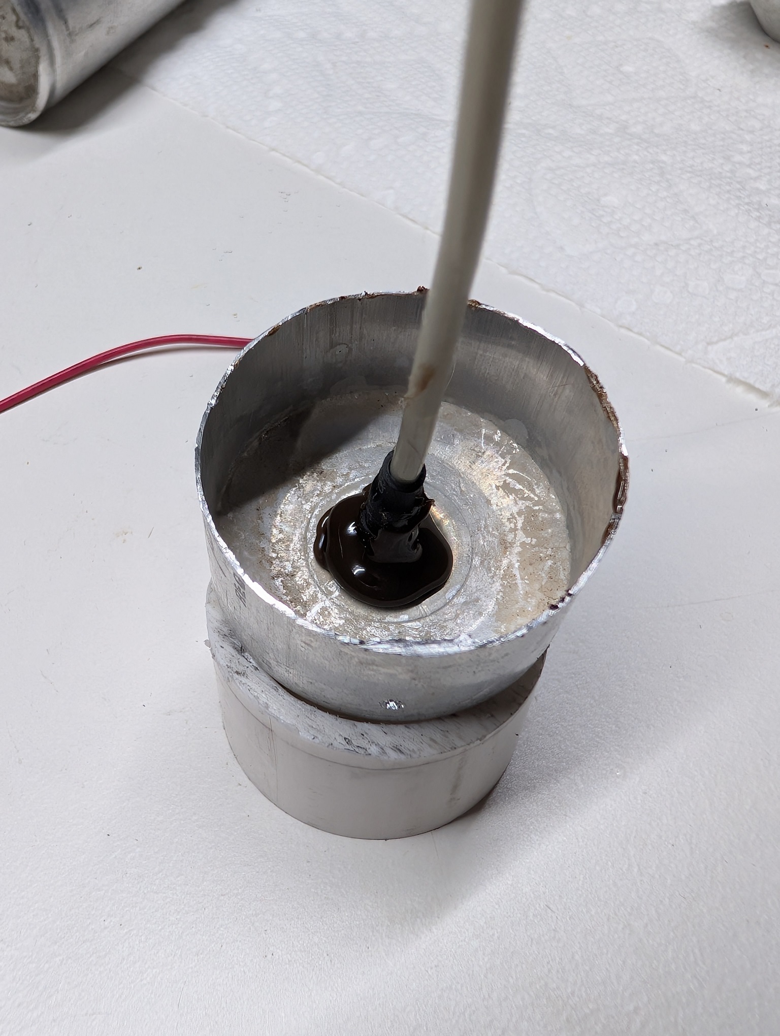
Put the negative wire with a foil pad, and glue in the 1" pipe insert.
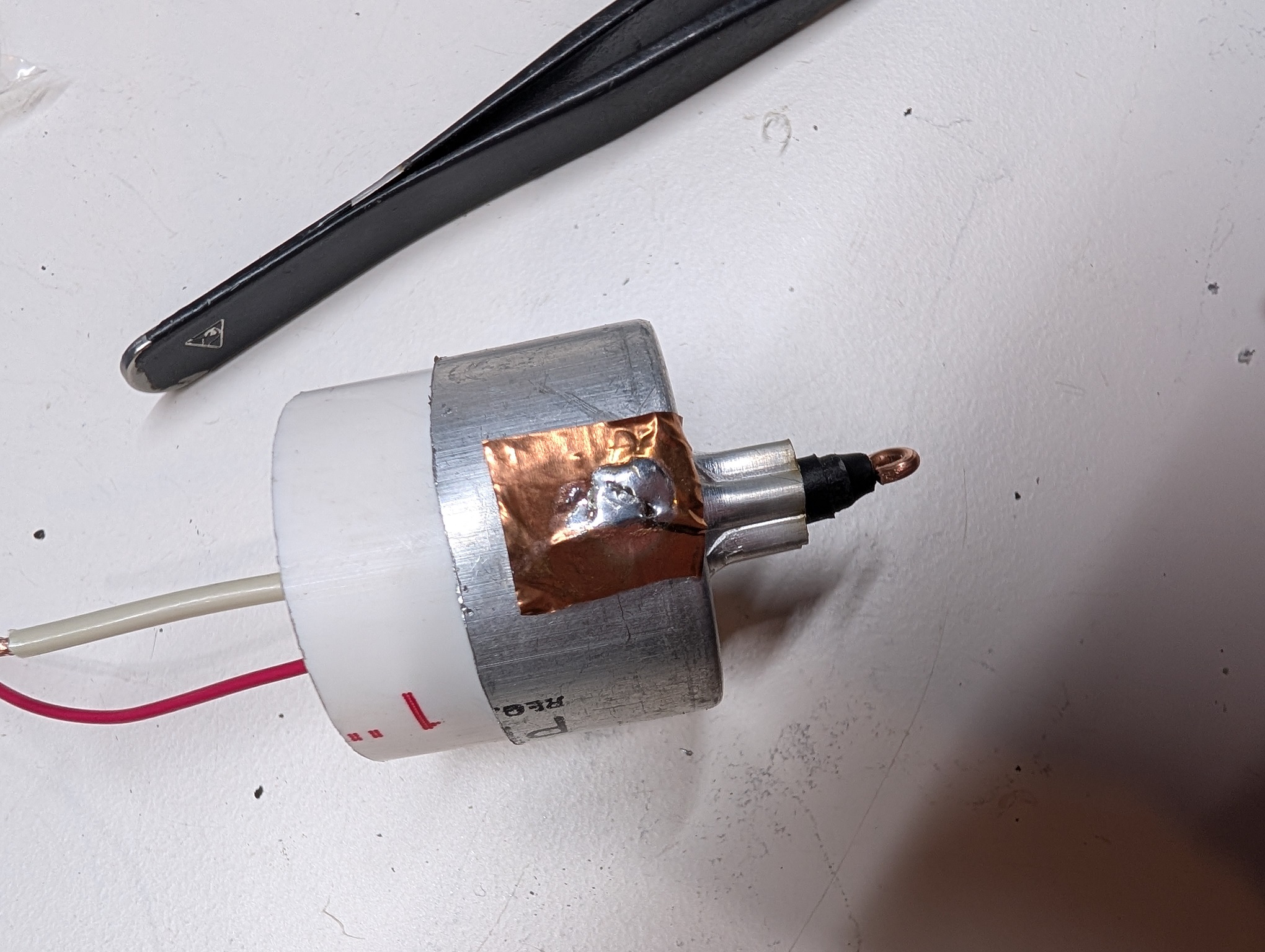
Then solder in the caps. This one is the 8uF replacement, so I use 2x 22uF high ripple Panasonics, that gives me 11uF, quite acceptable.
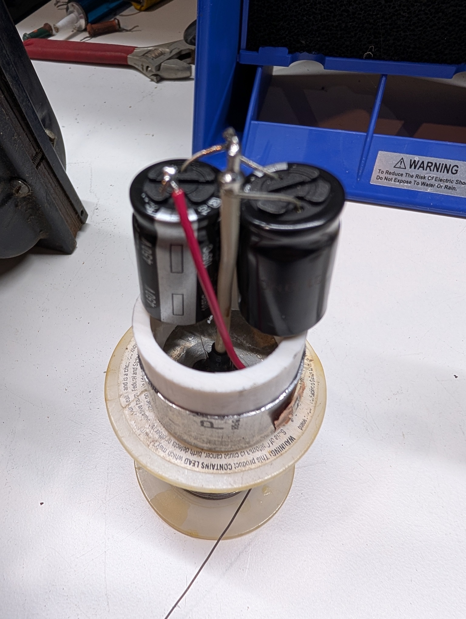
Then glue the halves together.

Both caps finished. For the second cap I use one 22uF cap; I have a lot, and the second cap can be of a larger value, as this is at the filter's output.
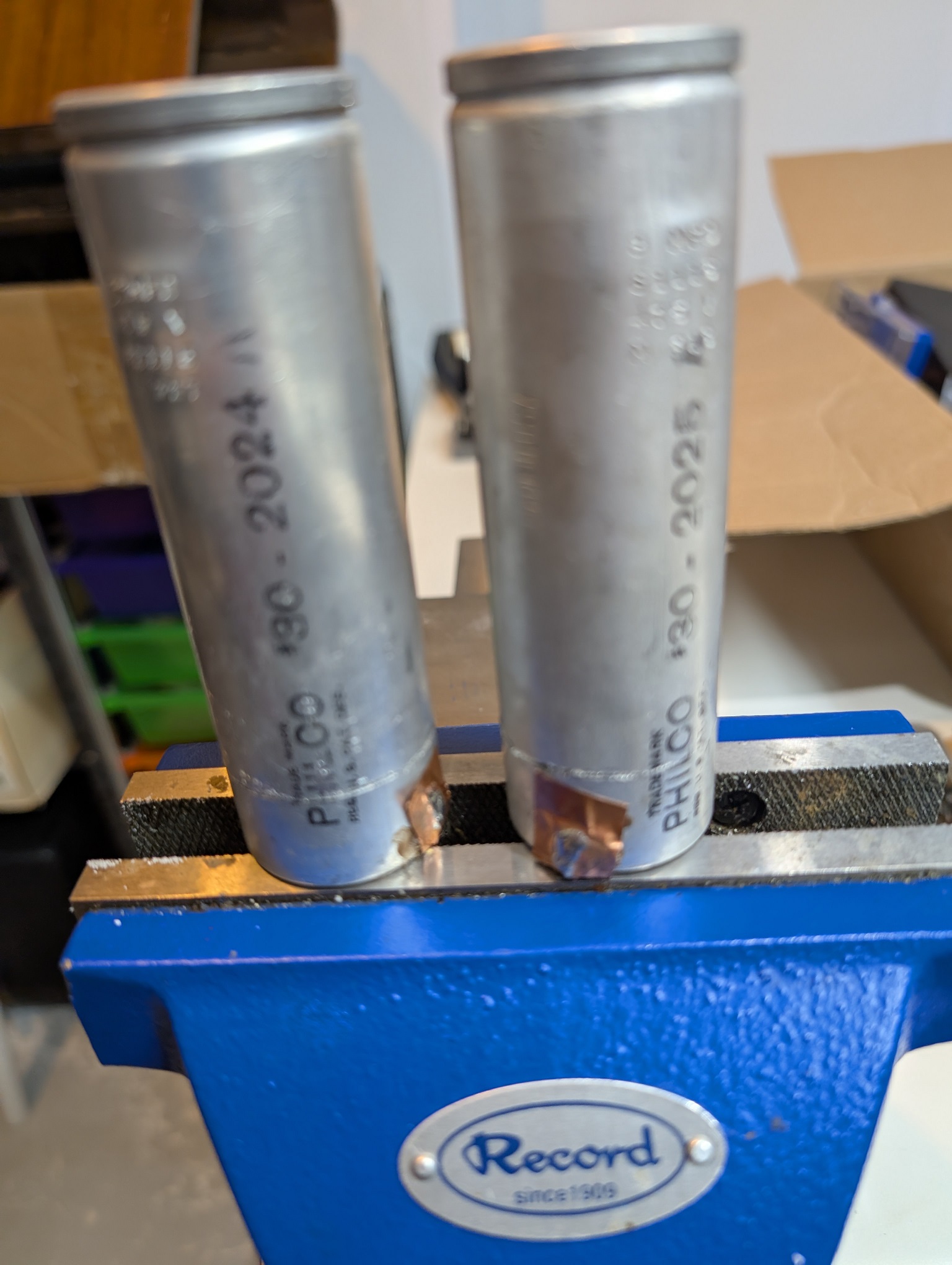
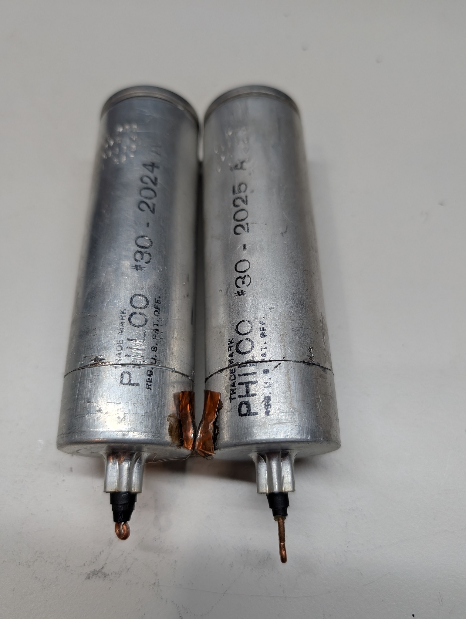
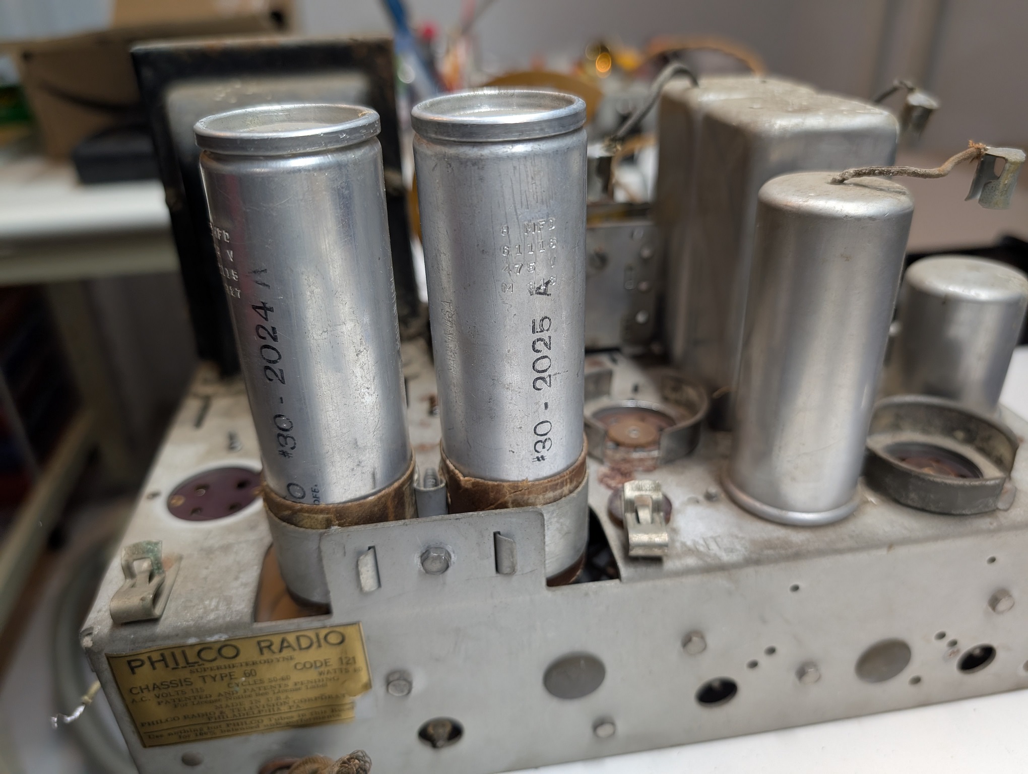
Installed, top and bottom.
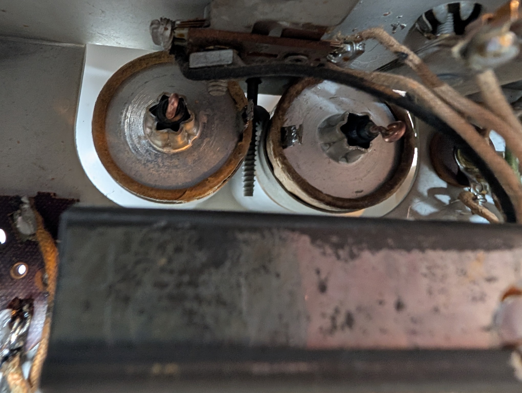
And soldered to.
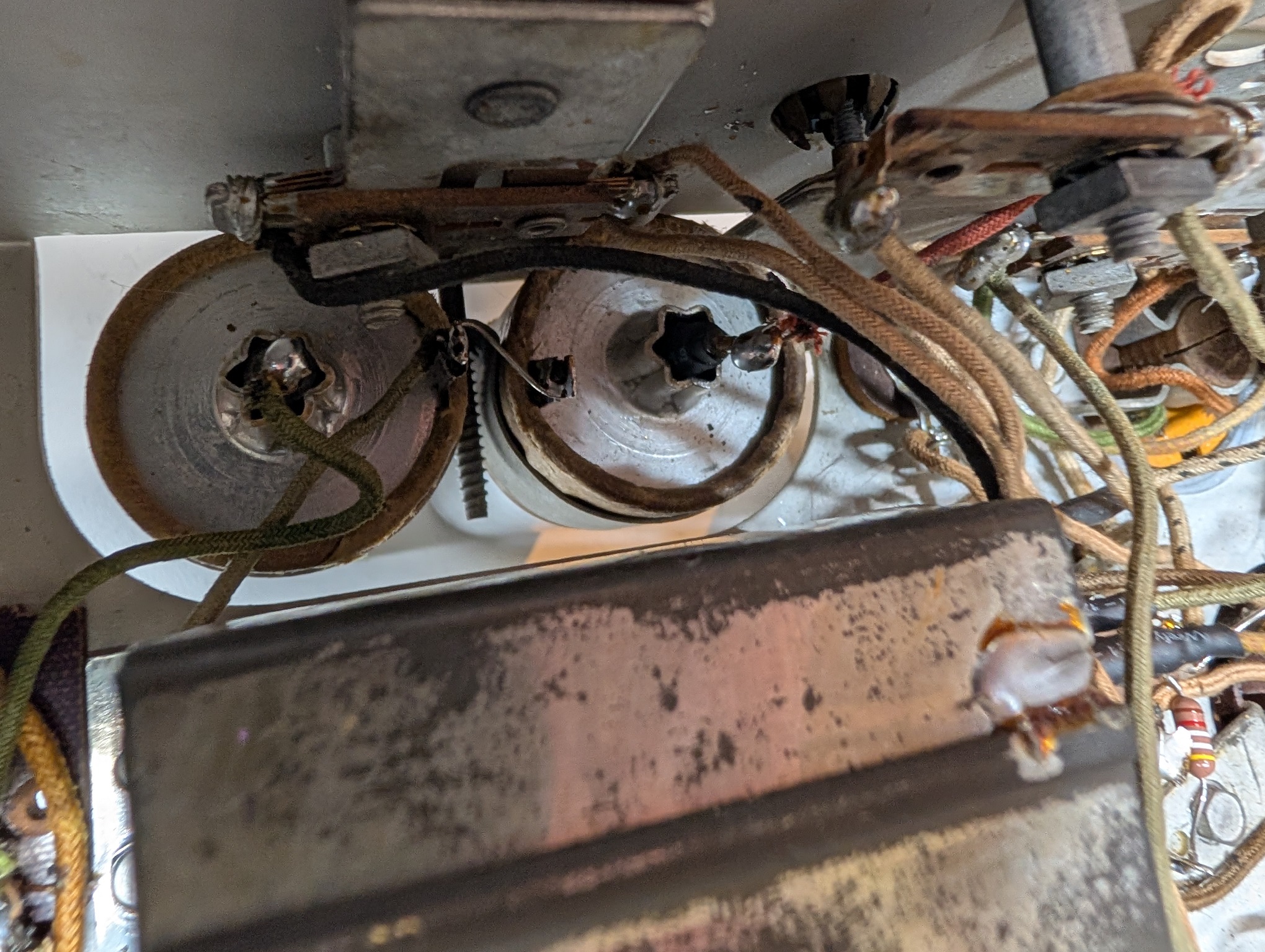
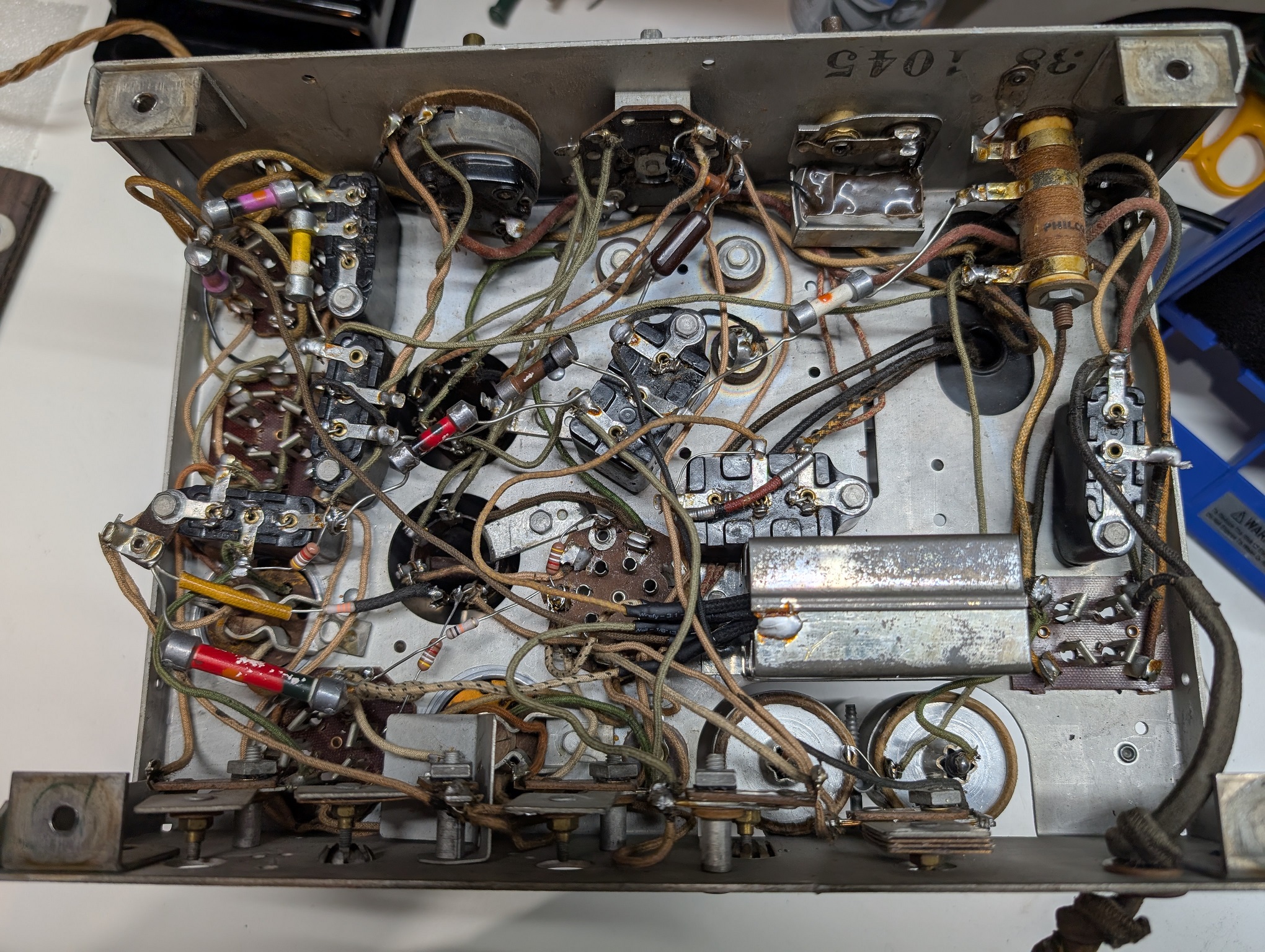
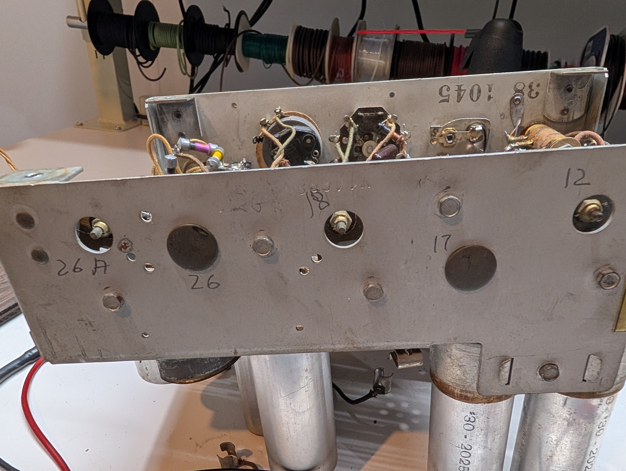
Now, when soldering the second cap and tracing wires, I realized the trimmer layout (the positive of the second cap goes to one of the trimmers, that connects to B+) is not one of those found here in the "60 EVolution" article.
https://philcoradio.com/library/index.ph...-model-60/
This is again the bottom view, the trimmers are shown.

And this is the back, with the traced trimmer numbers.
I think I have Run 6, with a 26A trimmer and 5 caps in the capacitive block.
However the layout of the trimmers is not the same shown on the pictures in the article.
Now, I will quickly check the coils, shorts at the power and will attempt the power up. (important step: while soldering the second cap's plus to the trimmer I realized it was shorted to GND. The investigation showed, it was touching the protective cap).
Had to go to Lowes and by a plastic 1" pipe to help hold the caps together when glued. It is 7' long and will probably last me 'till the rest of my life, as it takes under an inch for it to be used in this application.
Cut and opened the caps, cleaned out the guts and the plastic mesh, and soaked in vinegar.
For the center contact I use thick Romex copper wire.
To make it sit well in the center, I put 4 layers of two different adhesive heat shrinkable tubing.
Then I pot it from inside with hot glue, to immobilize.
Put the negative wire with a foil pad, and glue in the 1" pipe insert.
Then solder in the caps. This one is the 8uF replacement, so I use 2x 22uF high ripple Panasonics, that gives me 11uF, quite acceptable.
Then glue the halves together.
Both caps finished. For the second cap I use one 22uF cap; I have a lot, and the second cap can be of a larger value, as this is at the filter's output.
Installed, top and bottom.
And soldered to.
Now, when soldering the second cap and tracing wires, I realized the trimmer layout (the positive of the second cap goes to one of the trimmers, that connects to B+) is not one of those found here in the "60 EVolution" article.
https://philcoradio.com/library/index.ph...-model-60/
This is again the bottom view, the trimmers are shown.
And this is the back, with the traced trimmer numbers.
I think I have Run 6, with a 26A trimmer and 5 caps in the capacitive block.
However the layout of the trimmers is not the same shown on the pictures in the article.
Now, I will quickly check the coils, shorts at the power and will attempt the power up. (important step: while soldering the second cap's plus to the trimmer I realized it was shorted to GND. The investigation showed, it was touching the protective cap).
People who do not drink, do not smoke, do not eat red meat will one day feel really stupid lying there and dying from nothing.


![[-] [-]](https://philcoradio.com/phorum/images/bootbb/collapse.png)


