01-04-2025, 10:38 PM
I made a lot of progress on finalizing the schematic today. I have successfully verified the values of all resistors and capacitors in sections 1, 2, and 3 now. I caught a few more deviations from the original Philco schematic:
1. Per the production run notes, C316A was added in production run 5. This is a 240 pF, 500VDC mica capacitor (Philco part #60-10245307). It is to be installed in parallel with C316 "to prevent oscillation in FM operation". Subsequently, production run 8 indicates that C316 was removed but says nothing of C316A. I find it interesting, though, that I found a 240 pF capacitor installed in parallel with C317. I wonder if the writers of the documentation had meant to say that this 240 pF capacitor was supposed to be installed in parallel with C317. Regardless, I will keep it. I've added it to my schematic, in parallel with C317 as I discovered, but have instead called it C317A.
2. Also per the production run notes (run 4), an unnamed 100 pF capacitor was added between the high-potential terminal of the volume potentiometer and the 1 MΩ hard tap "to improve high frequency audio response". This capacitor never appeared in any of the Philco schematics, but I found it in my radio. C207 was the next available name in the 200's, so that's the name I've assigned to it on my schematic. The documentation does indicate that it is Philco part #60-10105407, which is a 100pF, 500VDC mica capacitor. I used my LCR meter to confirm its value. It was within about 6% of that.
3. Contrary to all of the available Philco schematics and parts lists for this radio, I have found that R305 is not a 150 Ω resistor. It is actually an 18 Ω resistor in my radio. Sure enough, the color bands were brown-grey-black. I also confirmed on my ohmmeter (it read 27 ohms, but it does prove that we are an order of magnitude off from the 180 Ω value in the Philco schematic). I got curious, so I also checked the Rider's schematics online. They also indicate that this should be a 150 Ω resistor. I wonder if someone installed the wrong part in this radio. Nonetheless, I have updated my schematic according to my finding.
I've made all of these corrections to my working copy of the schematic. I also realized that I made a mistake on the value of R303 on my schematic, so I fixed this. It is supposed to be 27 kΩ, but I had typed 37kV. The original Philco schematic had the correct value, so this was my mistake. I fixed that as well. See attached schematic. At this point, all I need to do is to start disassembling the RF chassis to confirm those values.
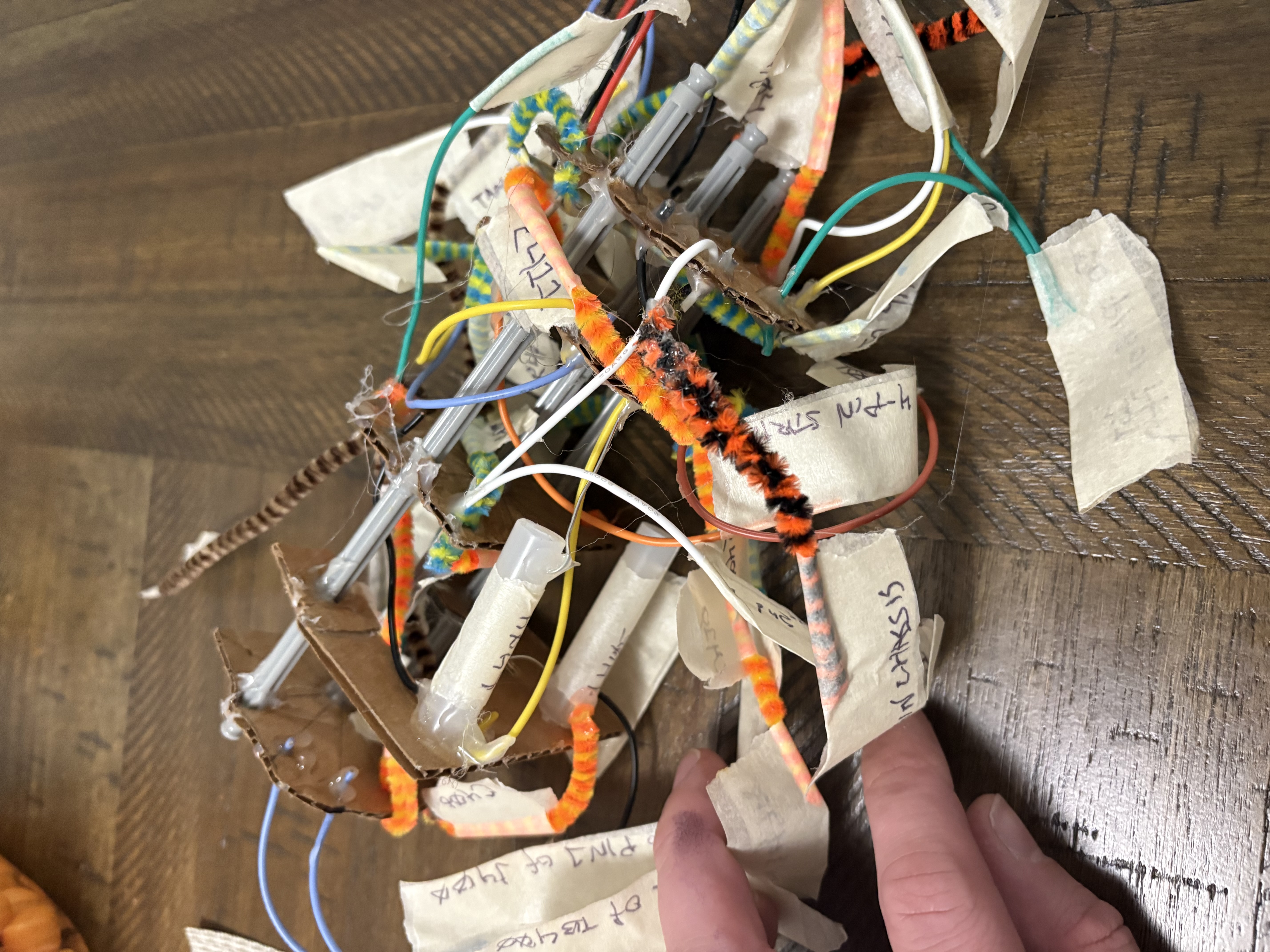
On that note, I still felt worried that I didn't have enough documentation to easily reconstruct the wafer switch assembly. After returning to my drawings the next day, I realized that much of the text was too small to easily follow. So, I created a model last night of the wafer switch. I created it to be exactly twice the scale of the actual unit, so that it's easier to look between the wafers. I have every wire colored correctly, and used pipe cleaners with tape labels (orange for capacitors, green for resistors) to model the components. I even have two little glue stick inductors! Now I am certain that I can reconstruct it!
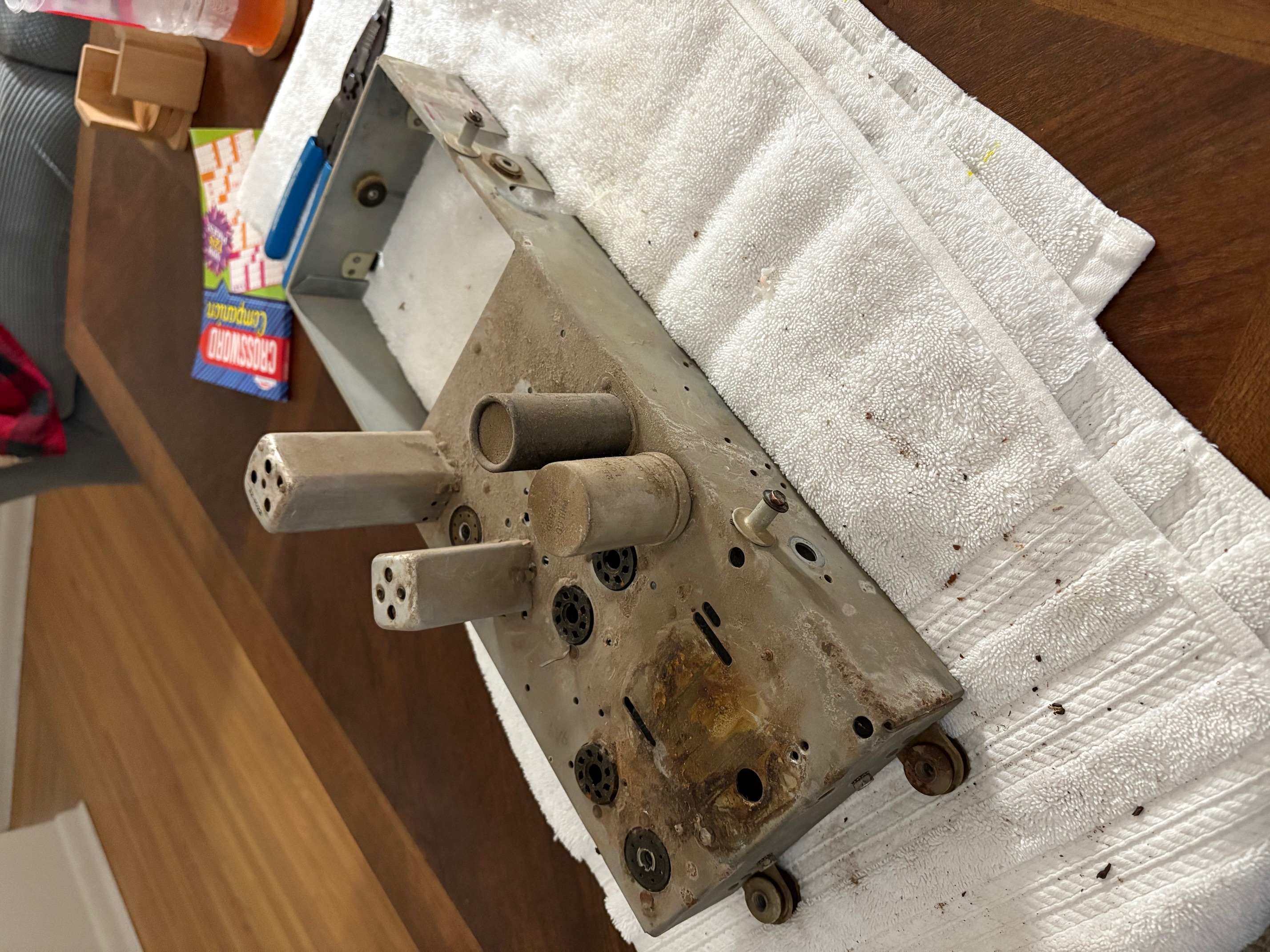
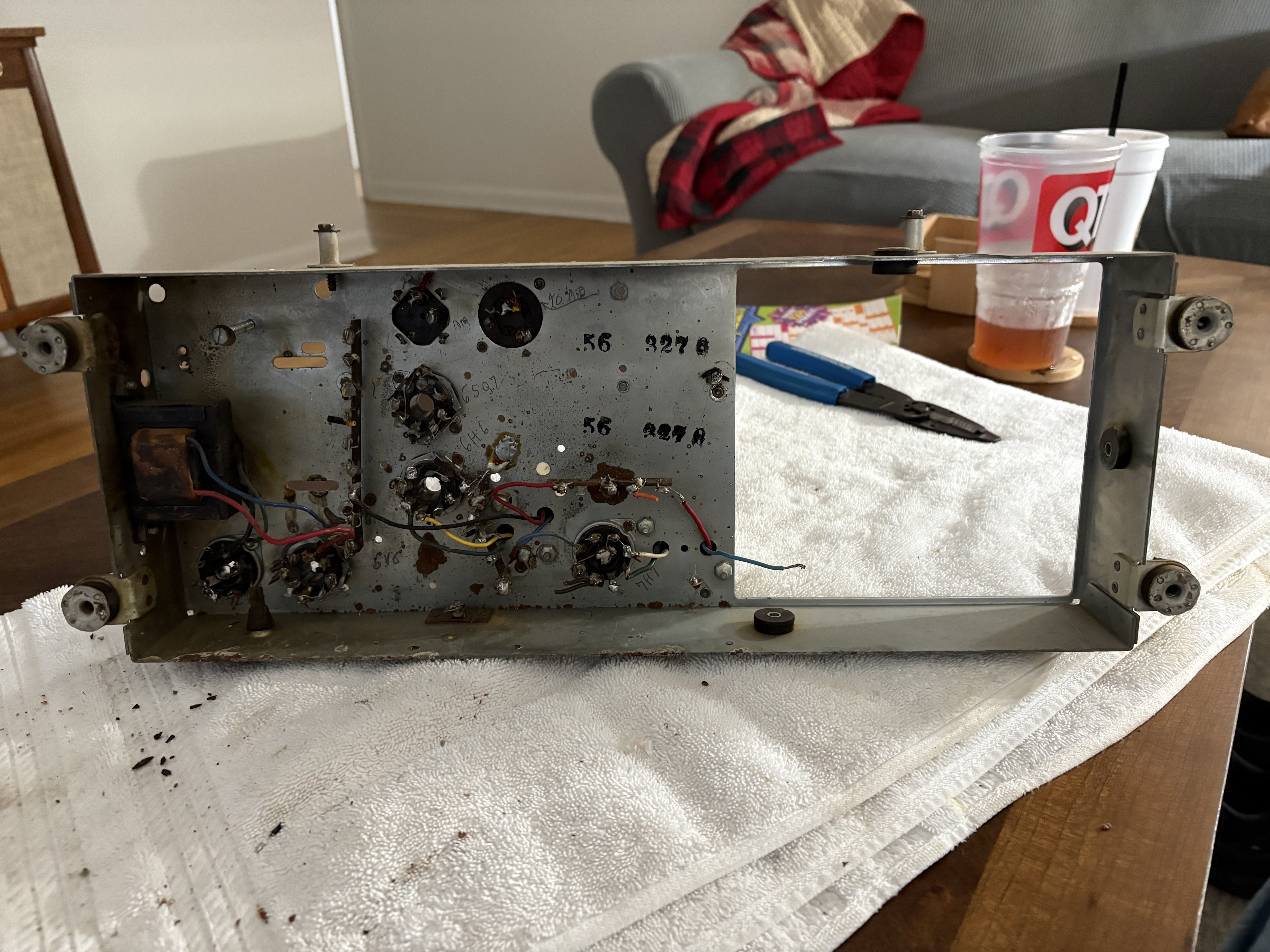
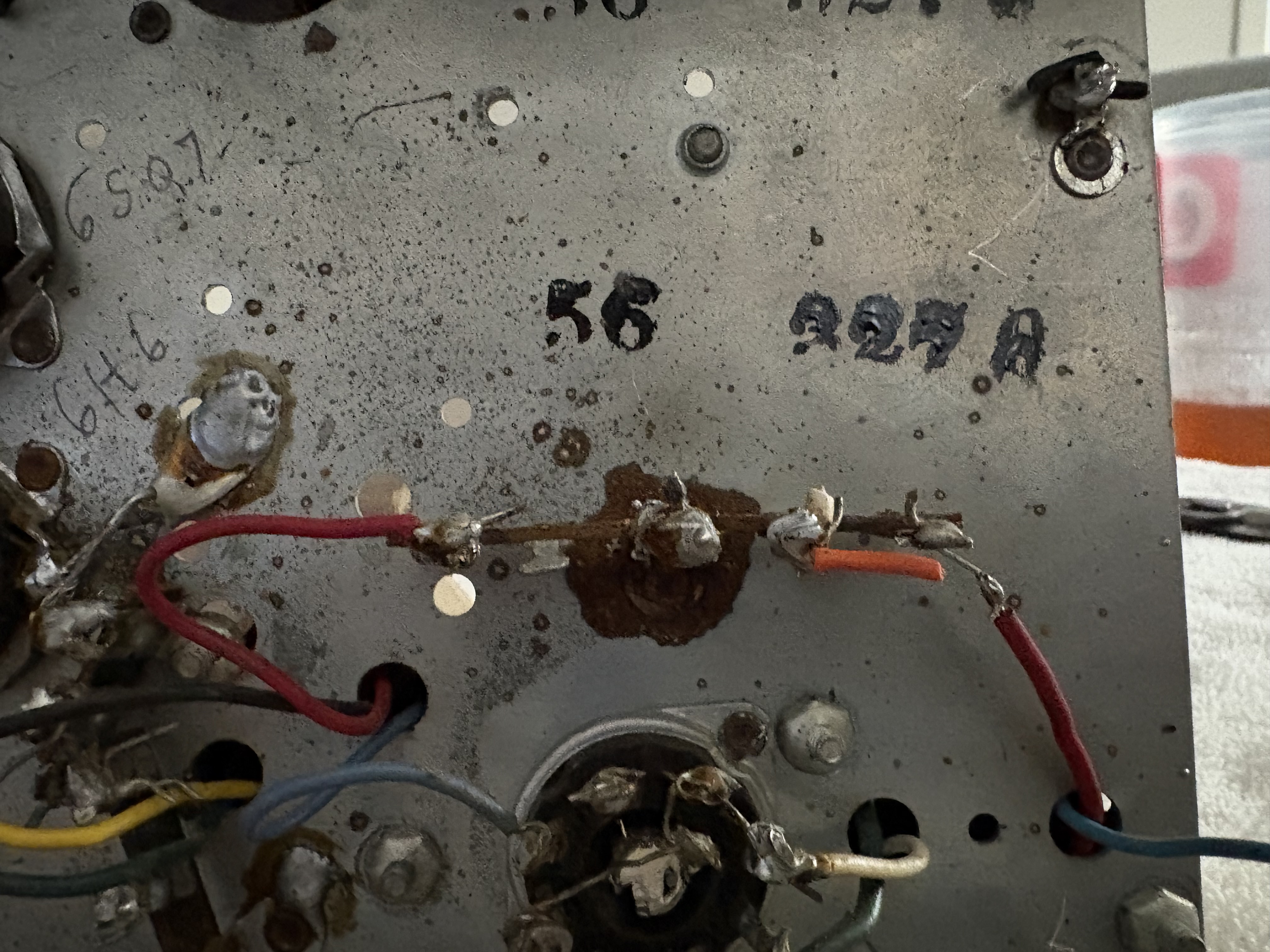
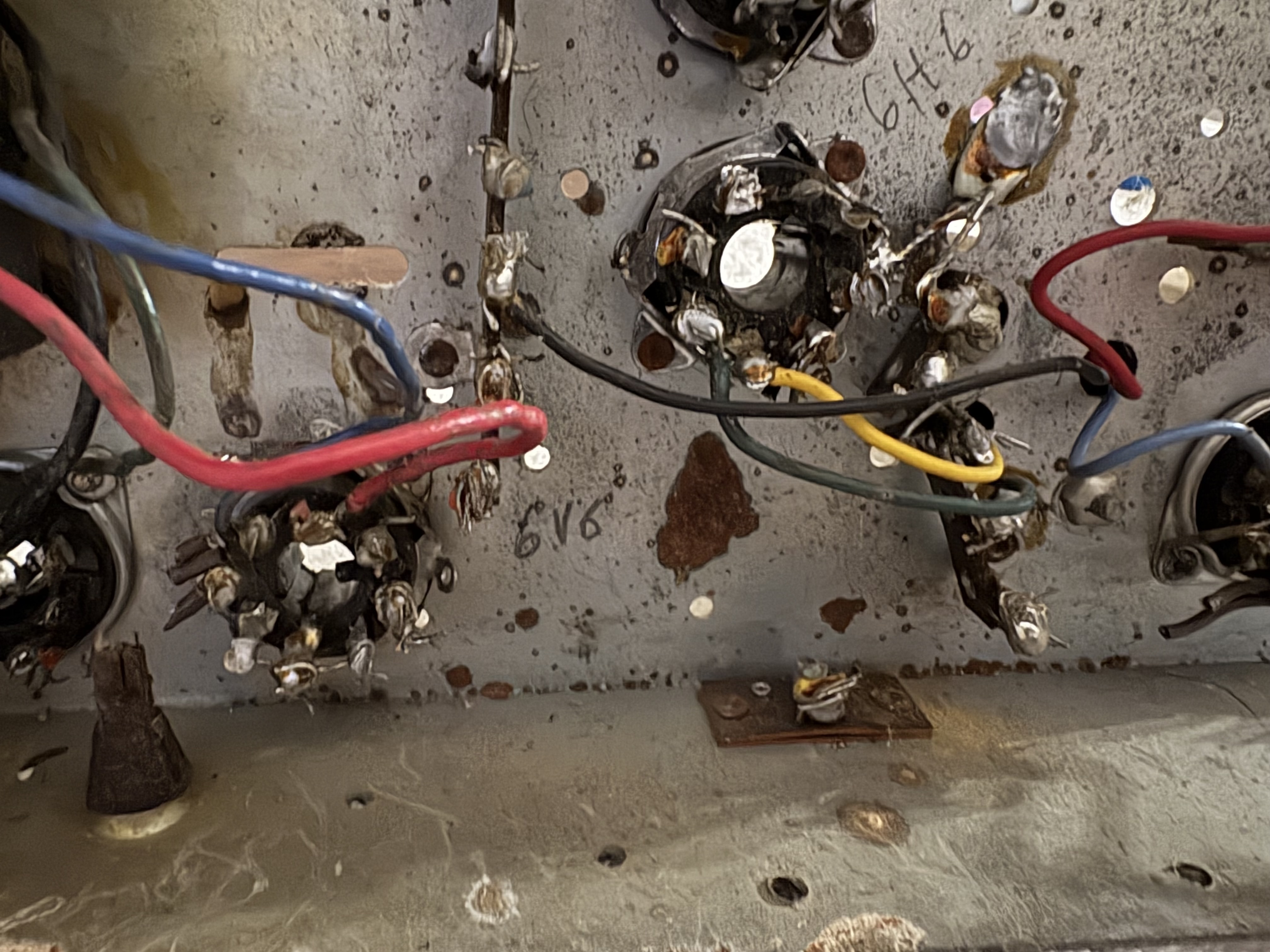
With that, I am almost ready to clean up the main chassis. I need to desolder the wires connecting to the IF cans and the audio output transformer. Then I can remove those few components. I'll drill out all of the rivets and clean the chassis. I notice that there's some areas of rust on the underside as well. Not to worry; it will get the same treatment of wire brushes, sandpaper, and naval jelly. But take a look at that one terminal strip. The grounded lug is riveted to the chassis, and that whole area is rusted! For certain, all of the connections to the chassis ground will need refreshed.
1. Per the production run notes, C316A was added in production run 5. This is a 240 pF, 500VDC mica capacitor (Philco part #60-10245307). It is to be installed in parallel with C316 "to prevent oscillation in FM operation". Subsequently, production run 8 indicates that C316 was removed but says nothing of C316A. I find it interesting, though, that I found a 240 pF capacitor installed in parallel with C317. I wonder if the writers of the documentation had meant to say that this 240 pF capacitor was supposed to be installed in parallel with C317. Regardless, I will keep it. I've added it to my schematic, in parallel with C317 as I discovered, but have instead called it C317A.
2. Also per the production run notes (run 4), an unnamed 100 pF capacitor was added between the high-potential terminal of the volume potentiometer and the 1 MΩ hard tap "to improve high frequency audio response". This capacitor never appeared in any of the Philco schematics, but I found it in my radio. C207 was the next available name in the 200's, so that's the name I've assigned to it on my schematic. The documentation does indicate that it is Philco part #60-10105407, which is a 100pF, 500VDC mica capacitor. I used my LCR meter to confirm its value. It was within about 6% of that.
3. Contrary to all of the available Philco schematics and parts lists for this radio, I have found that R305 is not a 150 Ω resistor. It is actually an 18 Ω resistor in my radio. Sure enough, the color bands were brown-grey-black. I also confirmed on my ohmmeter (it read 27 ohms, but it does prove that we are an order of magnitude off from the 180 Ω value in the Philco schematic). I got curious, so I also checked the Rider's schematics online. They also indicate that this should be a 150 Ω resistor. I wonder if someone installed the wrong part in this radio. Nonetheless, I have updated my schematic according to my finding.
I've made all of these corrections to my working copy of the schematic. I also realized that I made a mistake on the value of R303 on my schematic, so I fixed this. It is supposed to be 27 kΩ, but I had typed 37kV. The original Philco schematic had the correct value, so this was my mistake. I fixed that as well. See attached schematic. At this point, all I need to do is to start disassembling the RF chassis to confirm those values.
On that note, I still felt worried that I didn't have enough documentation to easily reconstruct the wafer switch assembly. After returning to my drawings the next day, I realized that much of the text was too small to easily follow. So, I created a model last night of the wafer switch. I created it to be exactly twice the scale of the actual unit, so that it's easier to look between the wafers. I have every wire colored correctly, and used pipe cleaners with tape labels (orange for capacitors, green for resistors) to model the components. I even have two little glue stick inductors!
With that, I am almost ready to clean up the main chassis. I need to desolder the wires connecting to the IF cans and the audio output transformer. Then I can remove those few components. I'll drill out all of the rivets and clean the chassis. I notice that there's some areas of rust on the underside as well. Not to worry; it will get the same treatment of wire brushes, sandpaper, and naval jelly. But take a look at that one terminal strip. The grounded lug is riveted to the chassis, and that whole area is rusted! For certain, all of the connections to the chassis ground will need refreshed.
Joseph
Philco 46-480
Philco 49-906


![[-] [-]](https://philcoradio.com/phorum/images/bootbb/collapse.png)


