01-06-2025, 08:46 PM
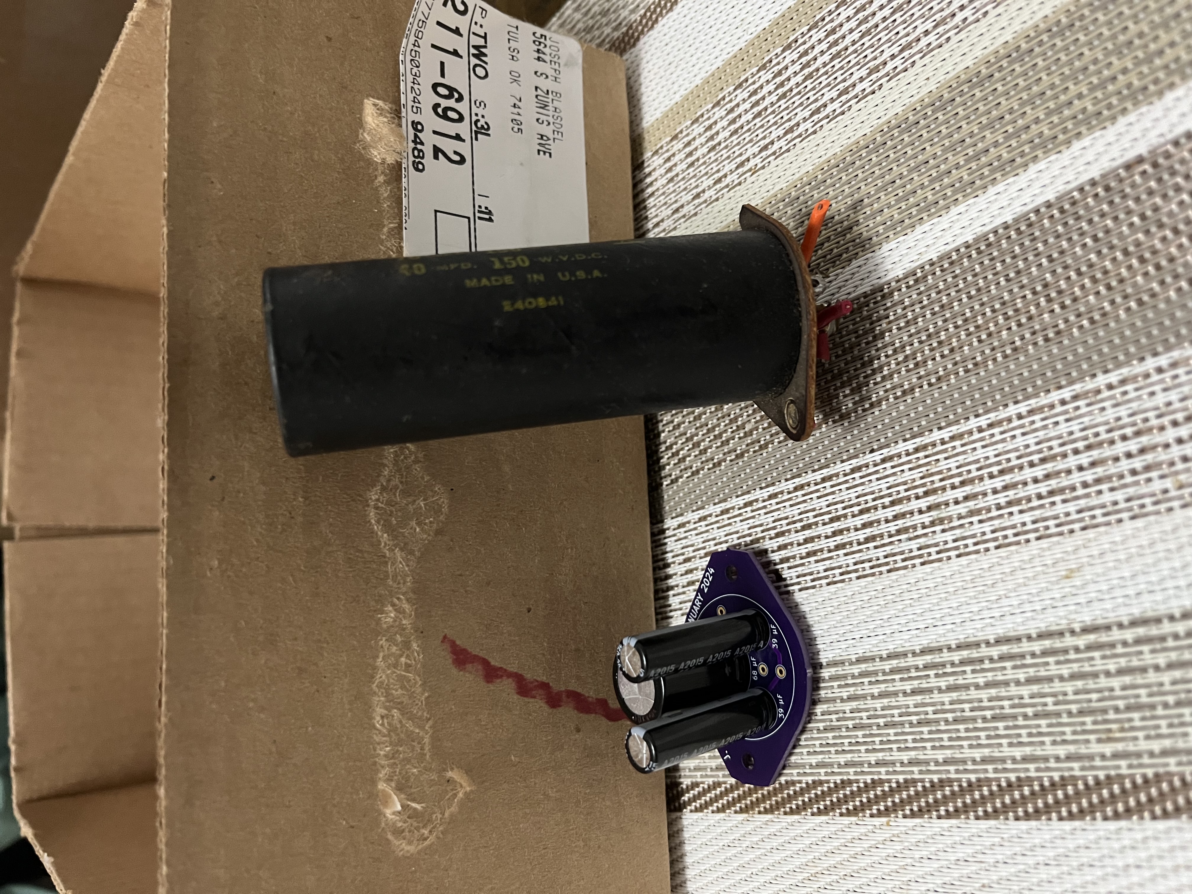
Today I momentarily shifted gears. I've been researching my options for new AC filter capacitors. When I replaced the big multi-section capacitor on my 49-906, I created a PCB onto which I soldered all of the individual electrolytics necessary to comprise an identical multi-section unit. The nice part was that I matched the shape and the through-holes for rivets.

However, the voltage across the capacitors on my 49-906 was a "mere" 115 VDC; for this 46-480, the voltage across the capacitors is 340 VDC. I suddenly realized that the dielectric material of the average PCB may not be rated to withstand these voltages.
Though I am an electrical engineer, I've never commercially designed a PCB. It's always been for personal reasons. So I reached out to OSH Park, who I typically use for producing PCB's. They did indicate that they are able to manufacture a PCB capable of safely handling these voltages. Furthermore, they provided me with some links to tools which will help with trace sizing, temperature increase, etc. I'll have to take my time to dissolve all of this. As usual, I'll share the process and results here.
Joseph
Philco 46-480
Philco 49-906


![[-] [-]](https://philcoradio.com/phorum/images/bootbb/collapse.png)


