01-19-2025, 08:53 PM
Thank you, Mike. I will order the fish paper. I saw that on Amazon, and admired the odd name.
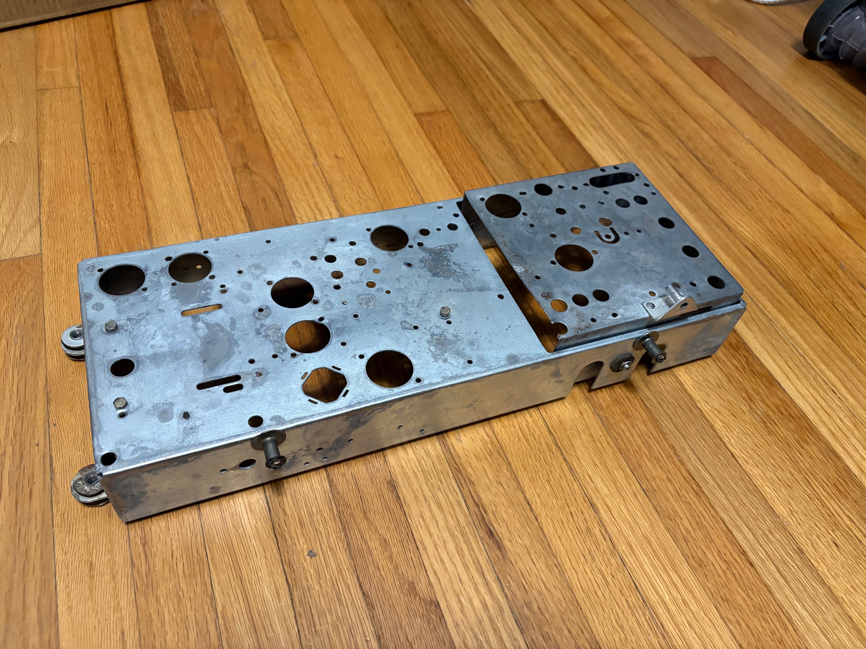
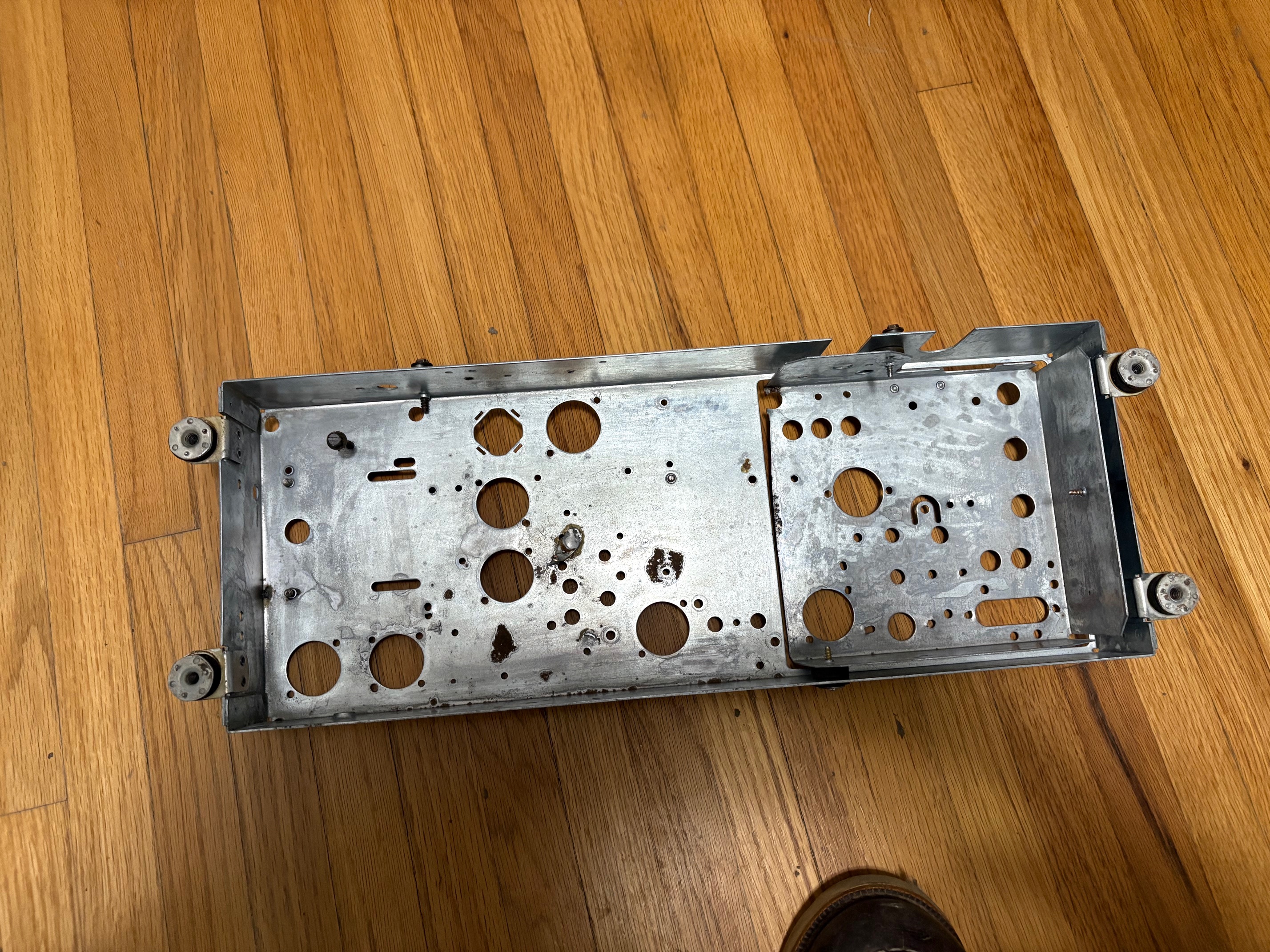
I should provide an update on the project. This week was fairly busy with work, so I felt that I wasn't able to spend as much time working on the radio in the evenings. Nonetheless, I finished disassembling the main and the RF chassis. Those were some very tough rivets to drill out! I knew that it would get up to about 50 degrees on Wednesday, and then it was 61 degrees on Thursday. I read that it needs to be between 50 and 90 degrees to use naval jelly, so I rushed to get the two parts of the chassis ready to clean on Thursday. It was about 7:00 PM by the time I was ready on Thursday evening, and the temperature was cooling down and hovering right at 50 degrees. I got it done, though! I applied the jelly, let sit for 10 minutes, and then scrubbed it with steel wool. I let it sit for another 5 minutes, and then wiped it clean with a wet rag. There was still some remaining jelly, so I sprayed the chassis clean with a garden hose on my driveway.
There was still just a bit of rust, so I applied a bit of baking soda and scrubbed it into the metal. One more rinse, and it was looking pretty good! There's a couple of remaining spots of rust, but they look more black in color to me (that is, they don't look like normal red rust).
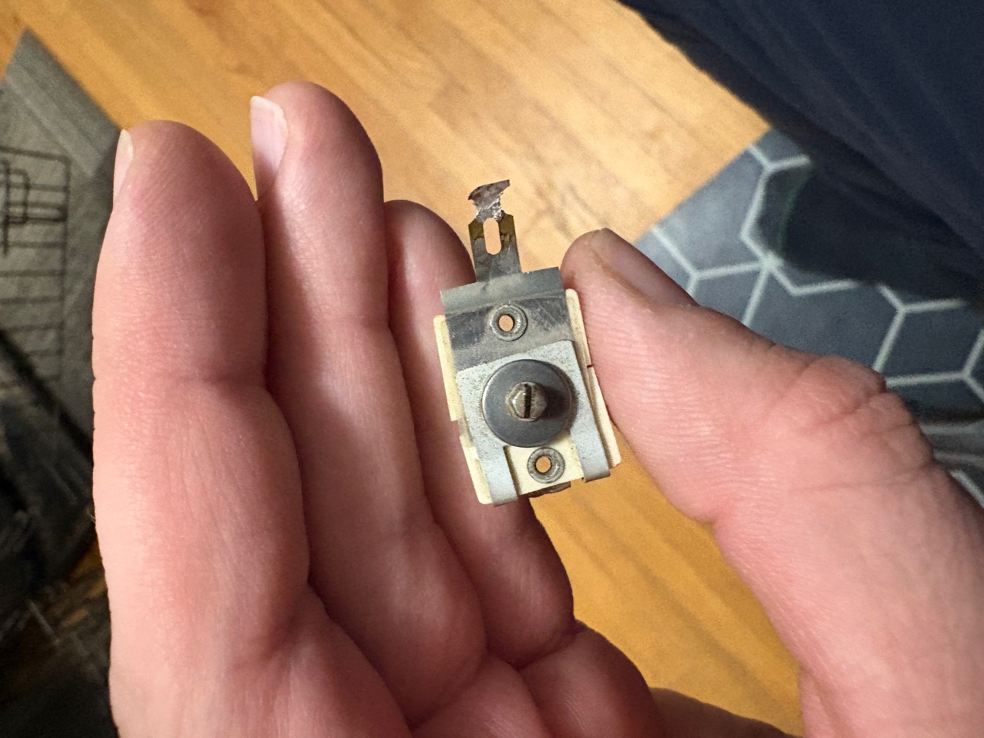
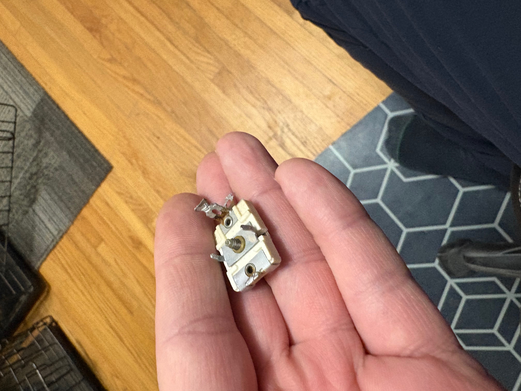
Aside from that, I have been cleaning up the components I'll be reusing (hardware, trim caps, the band wafer switch, the IF cans, etc.). There is an assembly of three trim capacitors named C404 A/B/C, and it is a Philco part number 31-6464. One of the three trimmers had a cracked housing. I was able to repair it with some super glue and a clamp. I then was able to reinsert it into the assembly and re-solder one side of it to the common frame. I made sure that it still adjusts (it does) and that it still appeared as an open circuit to DC.
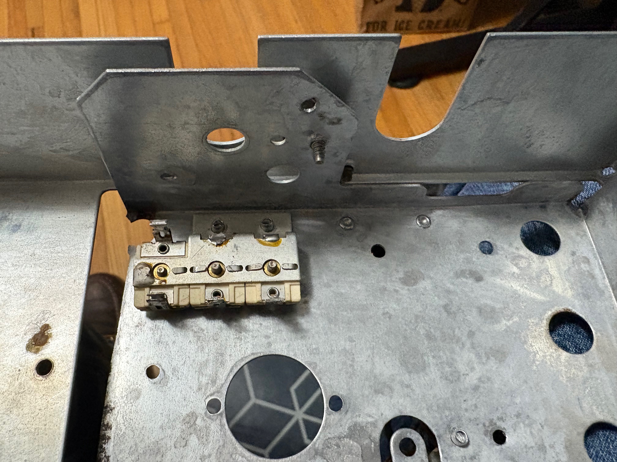
I used an LCR meter to start filling in some missing values on the schematic. C402A and C402B (both trimmer caps) both measure 10 pF. C404A and C404C measure 20pF, whereas C404B measures 600 pF (this unit is larger than the other two). As for inductors, L403, L406, L407, and L408 all measure 2.0 µH with a DC resistance of 0.1 Ω.
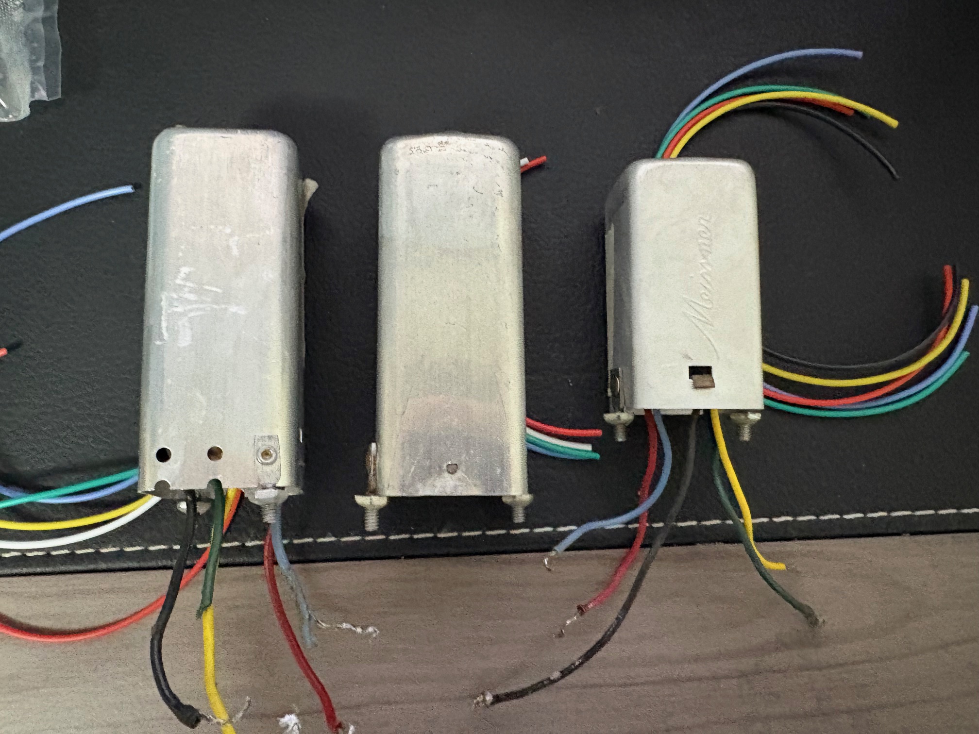
Lastly, I've removed the cans from all three IF cans. I cleaned them up in an ultrasonic bath of hot vinegar. They are looking nice! I've cleaned all of the trimmer caps in them with some electrical contact cleaner, and I have measured and cut 9" leads of new 20 AWG stranded wire for them. I need to order new capacitors to replace a few mica capacitors in two of them (might as well, while they are open).
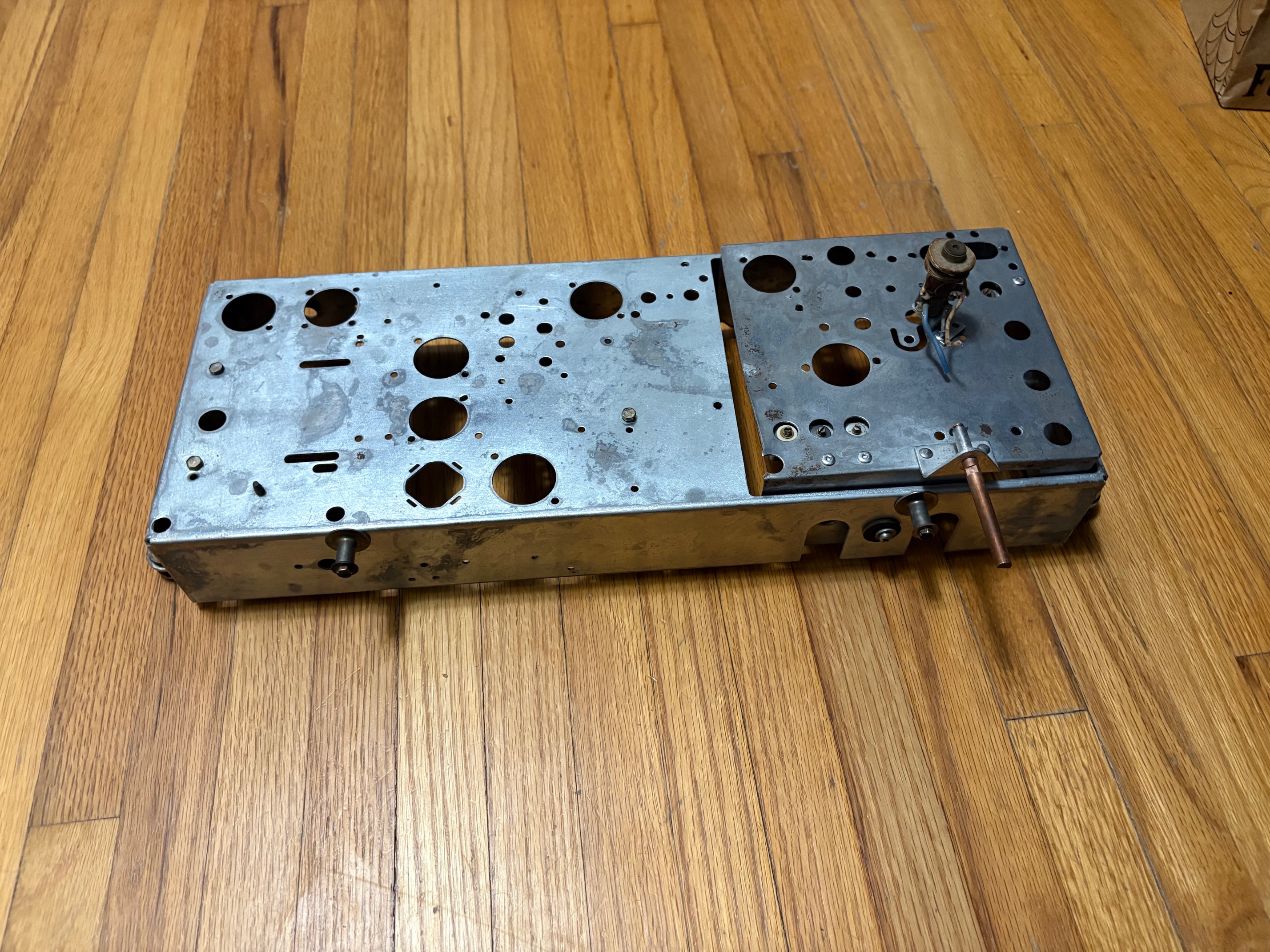
Lastly, I have finally disassembled the wafer switch. That is to say, I've removed all of the wires and passive devices connected to it. It's out in my garage, and I've been in the process of cleaning up all of the solder lugs so that it may be reused. I will also need to clean up the air gap tuning capacitor a bit, and then I'll reinstall it. But the chassis is now fully disassembled, is clean, and is looking pretty sharp with a few fresh rivets on it!
I should provide an update on the project. This week was fairly busy with work, so I felt that I wasn't able to spend as much time working on the radio in the evenings. Nonetheless, I finished disassembling the main and the RF chassis. Those were some very tough rivets to drill out! I knew that it would get up to about 50 degrees on Wednesday, and then it was 61 degrees on Thursday. I read that it needs to be between 50 and 90 degrees to use naval jelly, so I rushed to get the two parts of the chassis ready to clean on Thursday. It was about 7:00 PM by the time I was ready on Thursday evening, and the temperature was cooling down and hovering right at 50 degrees. I got it done, though! I applied the jelly, let sit for 10 minutes, and then scrubbed it with steel wool. I let it sit for another 5 minutes, and then wiped it clean with a wet rag. There was still some remaining jelly, so I sprayed the chassis clean with a garden hose on my driveway.
There was still just a bit of rust, so I applied a bit of baking soda and scrubbed it into the metal. One more rinse, and it was looking pretty good! There's a couple of remaining spots of rust, but they look more black in color to me (that is, they don't look like normal red rust).
Aside from that, I have been cleaning up the components I'll be reusing (hardware, trim caps, the band wafer switch, the IF cans, etc.). There is an assembly of three trim capacitors named C404 A/B/C, and it is a Philco part number 31-6464. One of the three trimmers had a cracked housing. I was able to repair it with some super glue and a clamp. I then was able to reinsert it into the assembly and re-solder one side of it to the common frame. I made sure that it still adjusts (it does) and that it still appeared as an open circuit to DC.
I used an LCR meter to start filling in some missing values on the schematic. C402A and C402B (both trimmer caps) both measure 10 pF. C404A and C404C measure 20pF, whereas C404B measures 600 pF (this unit is larger than the other two). As for inductors, L403, L406, L407, and L408 all measure 2.0 µH with a DC resistance of 0.1 Ω.
Lastly, I've removed the cans from all three IF cans. I cleaned them up in an ultrasonic bath of hot vinegar. They are looking nice! I've cleaned all of the trimmer caps in them with some electrical contact cleaner, and I have measured and cut 9" leads of new 20 AWG stranded wire for them. I need to order new capacitors to replace a few mica capacitors in two of them (might as well, while they are open).
Lastly, I have finally disassembled the wafer switch. That is to say, I've removed all of the wires and passive devices connected to it. It's out in my garage, and I've been in the process of cleaning up all of the solder lugs so that it may be reused. I will also need to clean up the air gap tuning capacitor a bit, and then I'll reinstall it. But the chassis is now fully disassembled, is clean, and is looking pretty sharp with a few fresh rivets on it!
Joseph
Philco 46-480
Philco 49-906


![[-] [-]](https://philcoradio.com/phorum/images/bootbb/collapse.png)


