01-25-2025, 08:26 PM
It's been a long week of pulling out my hair, trying to decide what the engineers at Philco were thinking when they designed the 32-4074 IF transformer. But, at long last, I understand the design.
I have looked, but I could not find a single other model which uses this IF transformer. The only other 1946 model with FM reception, the model 46-1213, was different. I also looked into the 47-1227, because it was supposed to be included in the 1946 model year line-up but was delayed. It had a completely different design as well. I've looked at the 48-482 and the 49-906 as well, but the circuits they implement are quite different.
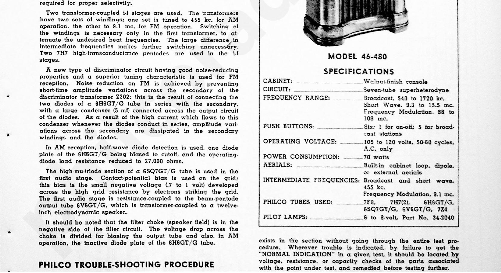
I'll open this discussion with a screenshot from the first page of the 46-480 service manual, which provides an explanation of the circuit. I'll refer back to this periodically.
In short, there are two factors which make this design very unique. First, there is no switching in any of the IF stages. The only switching between bands occurs just before the first IF stage. Second, AM and FM detection are accomplished with a total of two diodes via a 6H6GT/G tube. Most AM/FM sets at the time used other means, such as a double-diode/triode tube where the two diodes could be utilized for either a Foster-Seeley discriminator or a ratio detector for FM demodulation, and the triode could be used for either plate detection or grid leak detection of AM. Here's a screenshot of the aforementioned AM/FM detection portion of the 46-480.
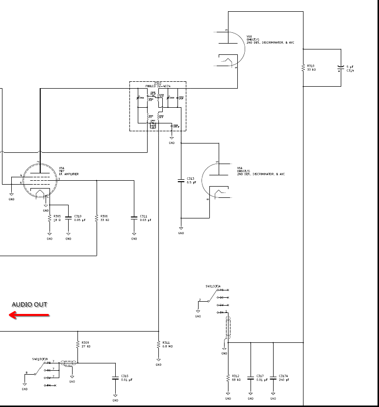
Notice that the third IF transformer is very strange. For one thing, AM and FM are crammed into a single IF can. It was very common for the first few years for AM and FM detection IF transformers to be combined into one single can. After a few years it became more common to separate AM and FM IF transformers into different cans. But, that said, the AM portion of this IF transformer is strange because it isn't a double-tuned resonant circuit. Pictured below is what I was expecting, one screenshot taken from the Philco model 49-906 schematic (because I also happen to have restored one of these) and the next from vintage-radio.com (specifically, https://www.vintage-radio.com/repair-res...tages.html)
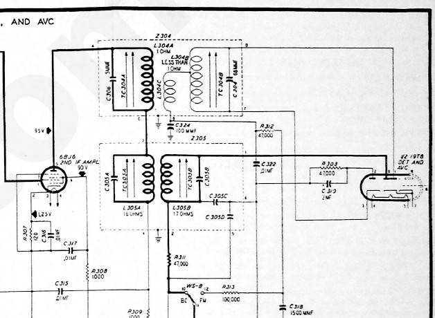
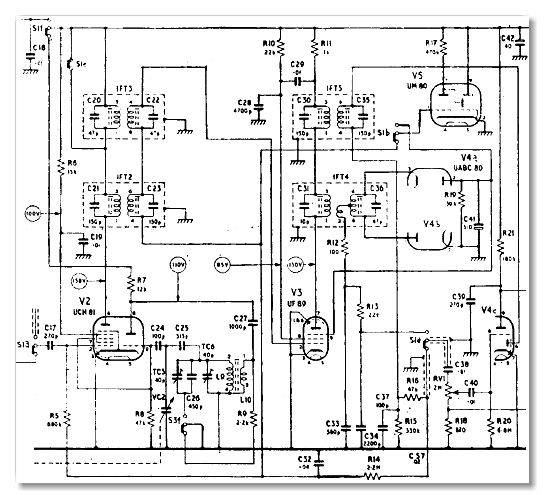
What I am trying to point out is that most AM/FM sets will stack two double-tuned resonant circuits, one for AM and another for FM (be it in one can or in separate cans). AM will be closest to the plate of the IF amplifier tubes, and FM will be closer to the B+ voltage source. I have spent the week trying to comprehend the 46-480's circuit, but here is a summary of what I have come to understand. I will split this into a summary of AM detection and a summary of FM detection. In AM operation, we have the following circuit.
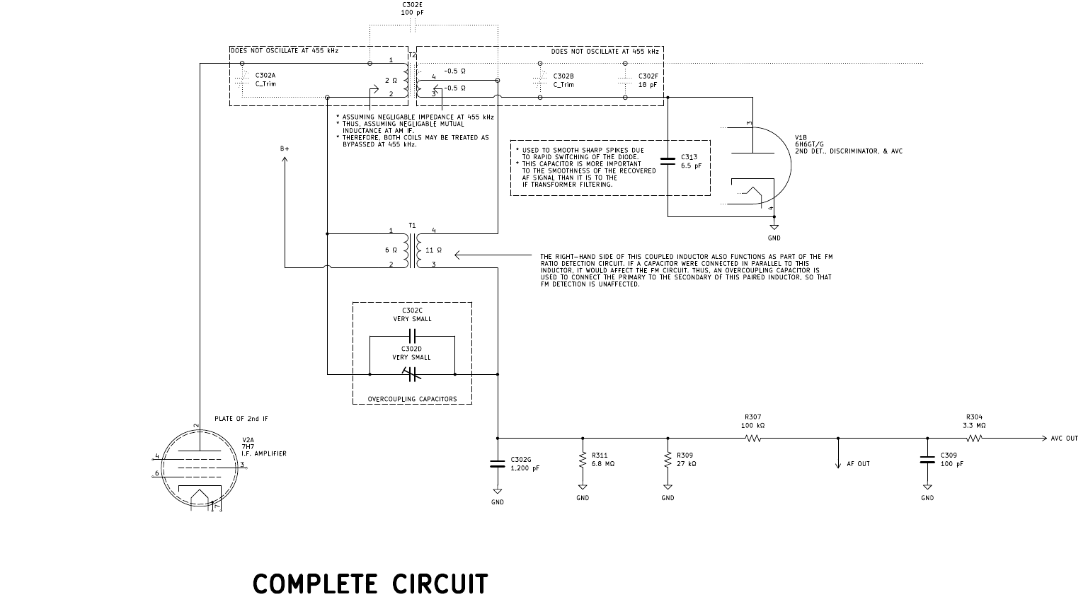
Right away I noticed that this is different from a "textbook" envelope detector circuit, seen in the below excerpt from one of my college textbooks (page 247 of "Introduction to Communication Systems", Third Edition by Ferrel G. Stremler).
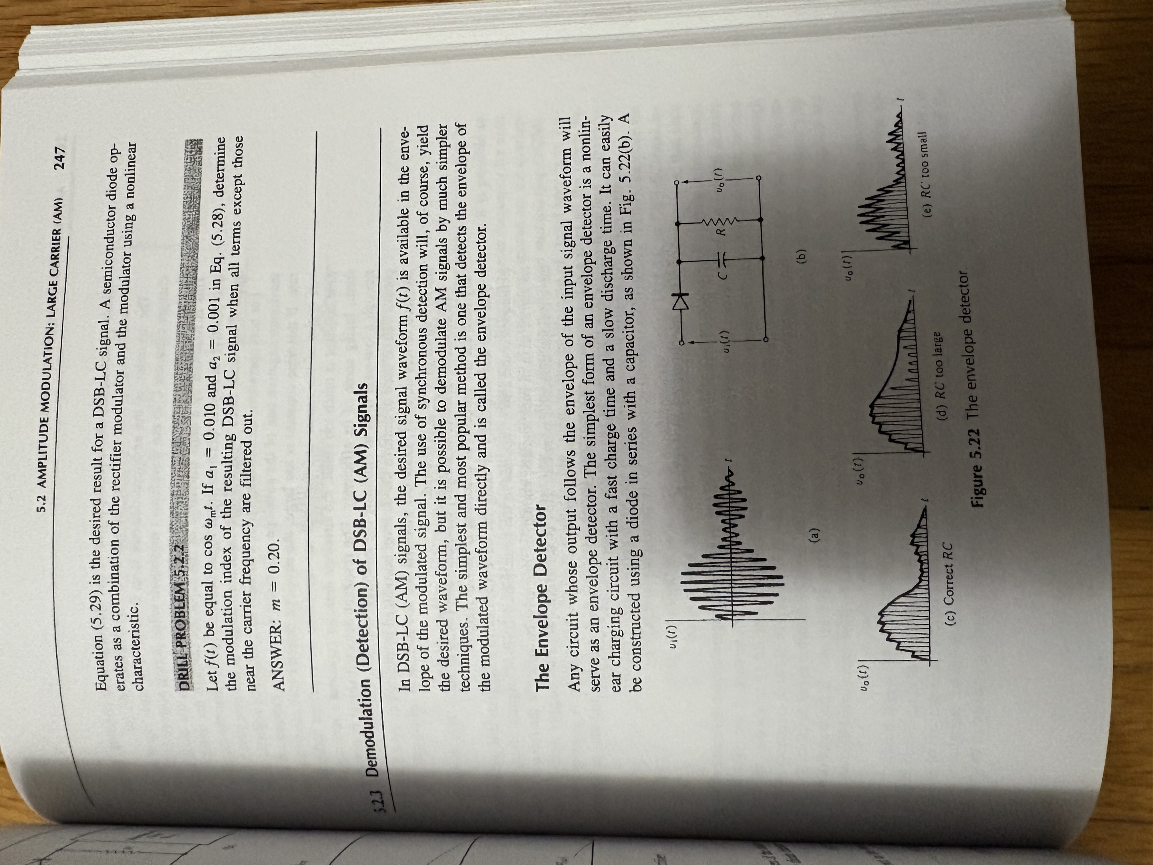
The circuit in the 46-480 is different, because the diode is not part of the signal through-path. It instead acts as a pull-down switch. I finally found such an arrangement on page 168 of "Old Time Radios!: Restoration and Repair", seen below.
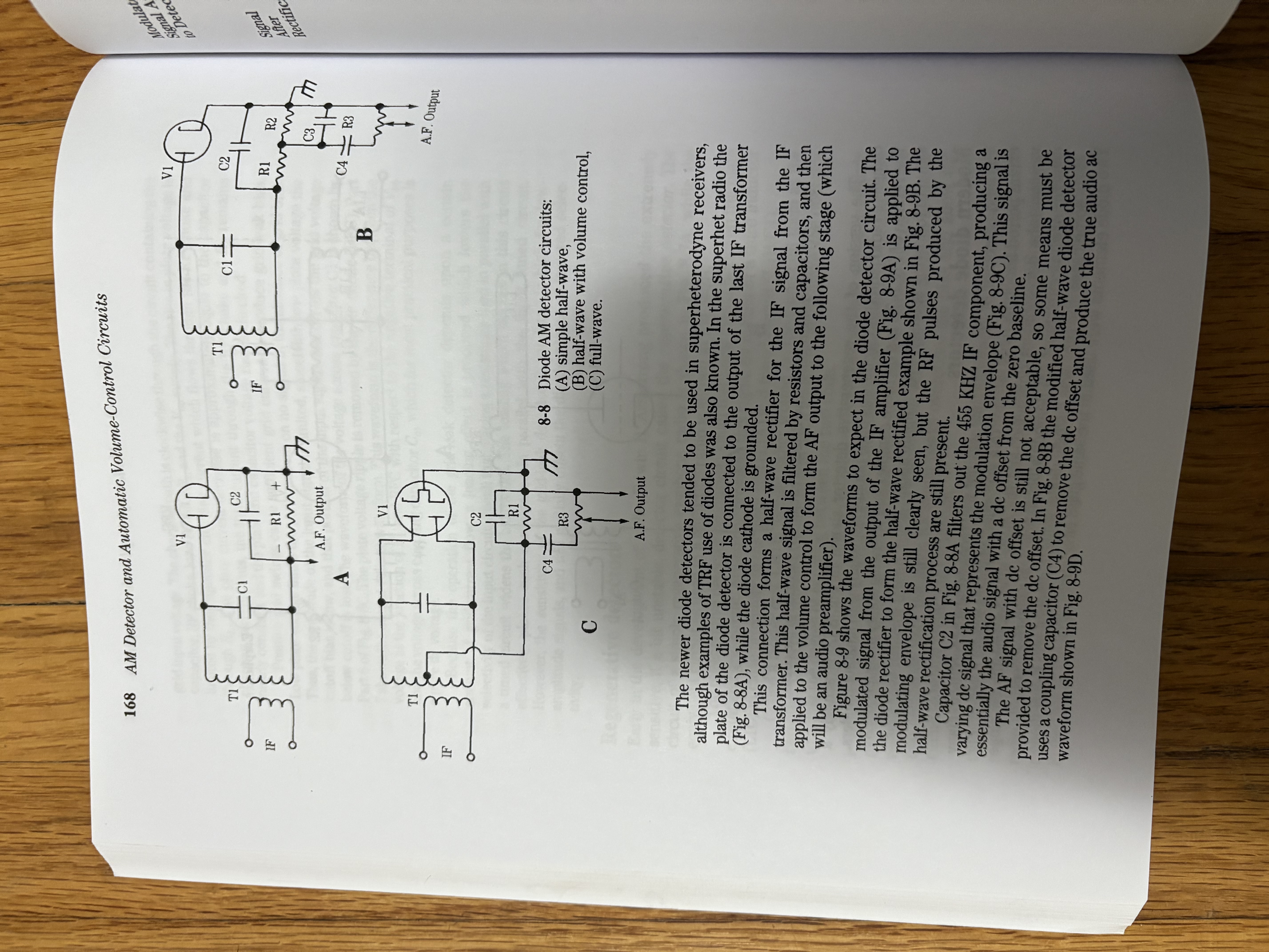
Having read up on the theory of this particular detector, I could return to analyzing the 46-480 circuit. Essentially, we have a diode half-wave detection of AM, with AVC feedback. As I have already mentioned, you will notice that the primary and secondary windings of T1 do not have capacitors connected in parallel to create resonant circuits. I was baffled for the longest time, but I now understand that it is because the secondary winding also functions as the RF choke coil for the FM circuit; if a capacitor were connected in parallel, it would disturb FM functionality. Thus, in lieu of parallel LC circuits on primary and secondary, capacitors C302C and C302D are inserted as "overcoupling" capacitors. C302D is a trimmer capacitor, so that the circuit can be tuned to couple at precisely the AM IF frequency of 455 kHz, while decoupling at the higher FM frequencies.
A couple of other things happen in AM operation. First, the diode between pins 3 and 4 of the 6H6GT/G is biased to cutoff (confirmed by reading the "General Information on Model 46-480" section on the last page of the attached service manual for this radio). This is accomplished by opening the plate connection to ground, instead forcing the plate to connect to ground through parallel resistance and capacitance. Second, R309 (27 kΩ) is connected to ground. R309 connects between the audio frequency output and ground. When it is grounded on one side in AM operation, it is essentially connected in parallel to R311 (6.8 MΩ), reducing the output resistance to just shy of 27 kΩ (confirmed in the circuit description from the first screenshot). Third, T2 features primary and secondary capacitors connected in parallel--these resonant circuits are not selected to resonate at 455 kHz, and are thus negligible to AM operation. I should also note that there is a small capacitor connected across the detection diode. After some research, I learned that this was often done for diode detectors with common cathodes because the diode is used as a pull-down switch and is thus subject to rapid fluctuations in capacitance compared to envelope detector circuits where the cathode outputs to a smoothing RC circuit. Below is the simplified circuit, showing only the components necessary for AM operation.
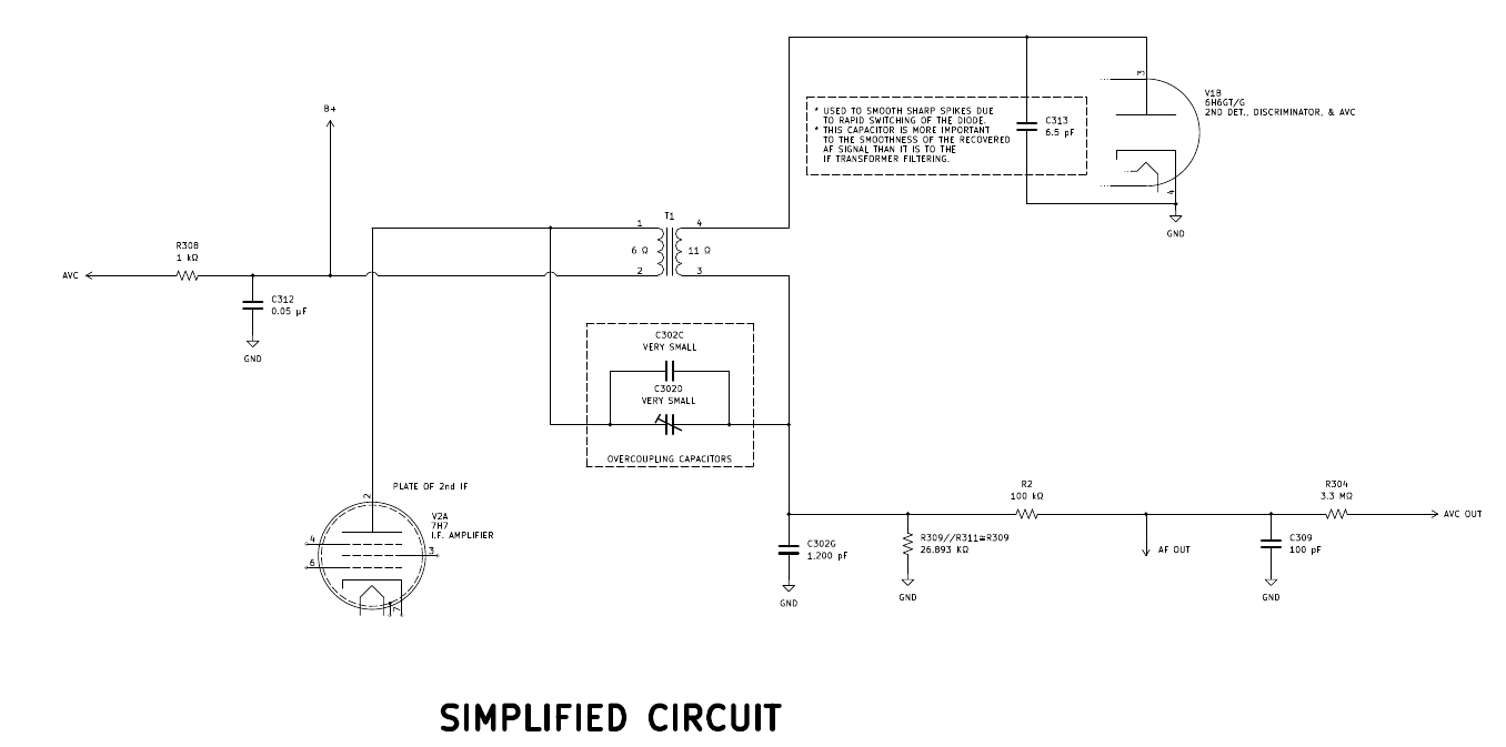
Now on to FM operation. Here's a screenshot of the FM detector circuit.
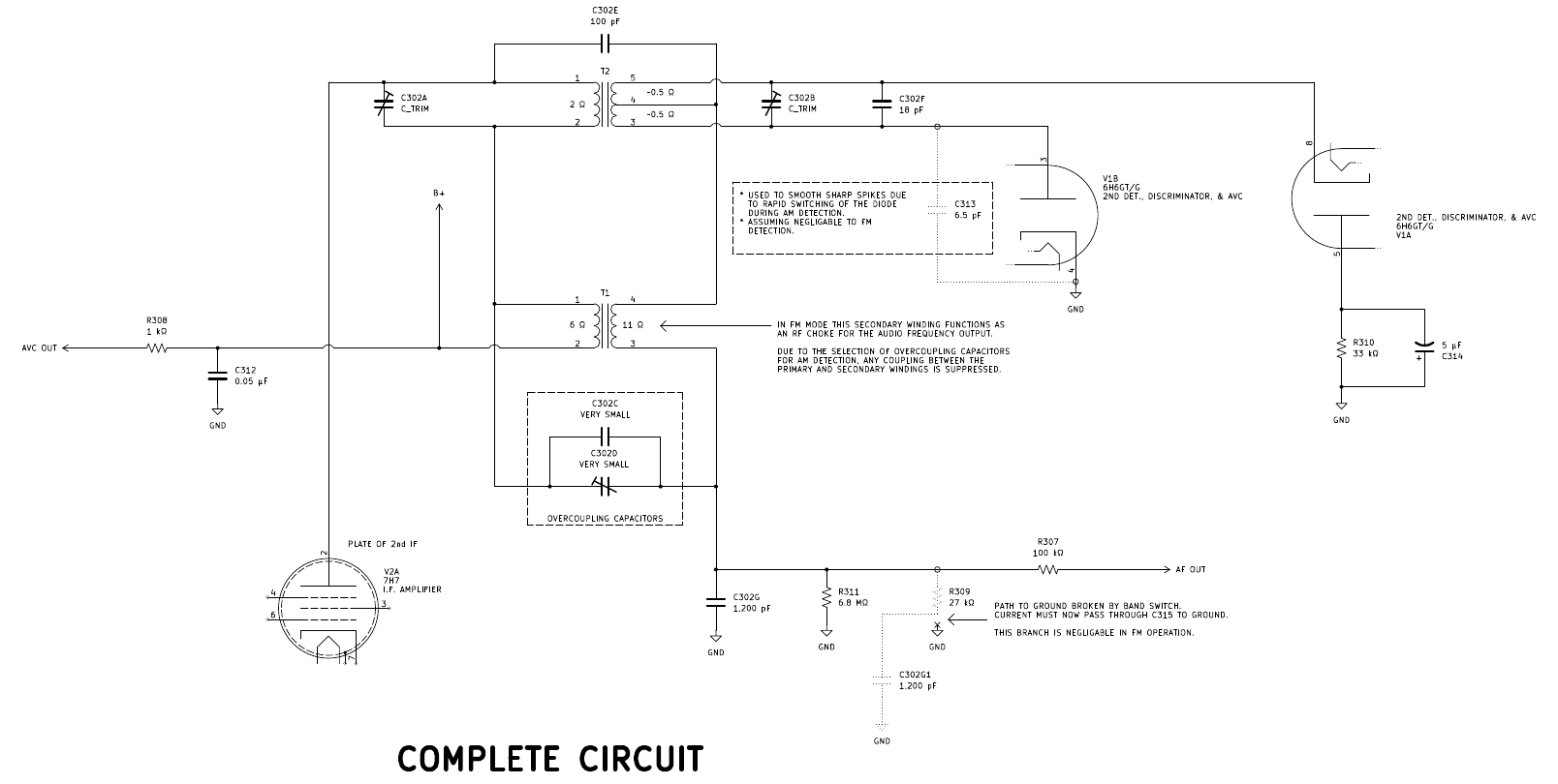
I can tell by the opposing diodes that this is a ratio detector circuit. But it's not quite the textbook version of a ratio detector. Again referencing "Introduction to Communication Systems", Third Edition, here's a picture of page 331 showing the typical ratio detector.
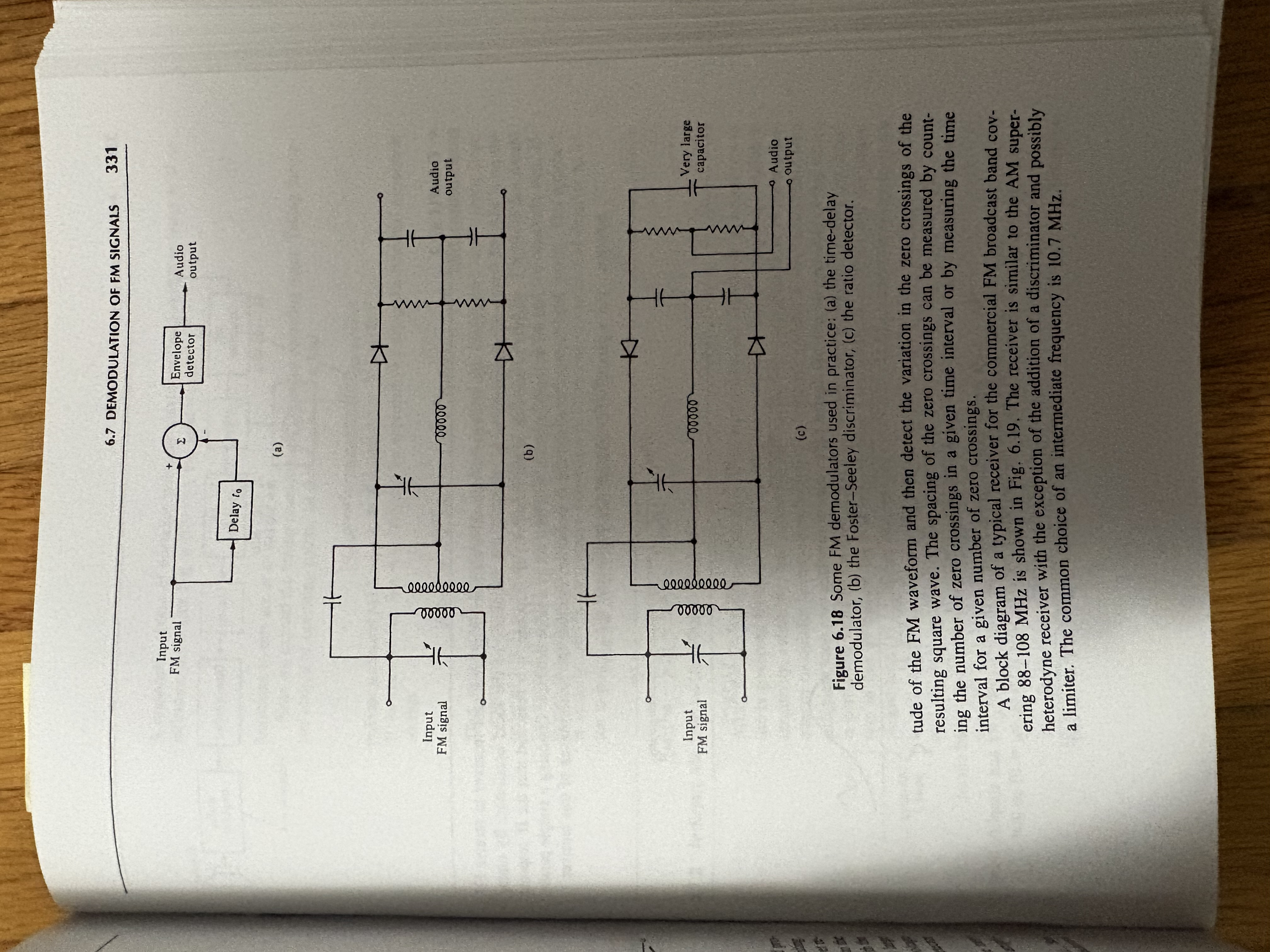
Notice that, to the right of the diodes, there are two capacitors connected in series with a center tap connecting to the output of the RF choke. These series capacitors are connected in parallel with the "very large" capacitor. They provide a sort of ratio, or voltage divider, allowing the voltage of the demodulated output to be a ratio of the total voltage across the "very large" capacitor. When analyzing the ratio detector circuit in the 46-480, I notice that there is no voltage divider created with two capacitors. There is only the single, "very large" capacitor (C314, 5 µF). Furthermore, there are also not two resistors connected in series between the two diodes; there is only a single resistor (R310, 33 kΩ). There are some variants of the ratio detector which have only one resistor. The only difference in functionality is that the reference voltage cannot be centered. In the case of the 46-480, the reference voltage is ground. But the lack of two series capacitors, connected in parallel to the "very large" capacitor really had me stumped.
Enter a 1951 copy of a Philco service manual (attached to this thread and screenshot below this paragraph). It detailed a few variations Philco used of the Foster-Seeley discriminator and the ratio detector, and actually included this exact arrangement. The ratio detector circuit can still function if the output voltage of the RF choke is solidly referenced to the cathode of the diode with the grounded cathode via a resistor and capacitor. And, what would you know, the 46-480 does exactly this (C302G, 1,200 pF and R311, 6.8 MΩ)!
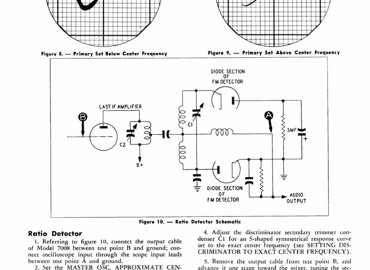
Now that I established what variant of the ratio detector circuit was being used, it was time to think about how the IF transformer came into play. The primary and secondary windings of T2 each feature a capacitor connected in parralel to create a double-tuned resonant circuit. Contrary to the AM transformer, the FM transformer can be arranged this way because the windings of T2 have no function to AM detection. From there, the ratio detector outputs a signal into the RF choke (Secondary winding of T1). Below is the simplified circuit, reduced to showing only the components necessary for FM.
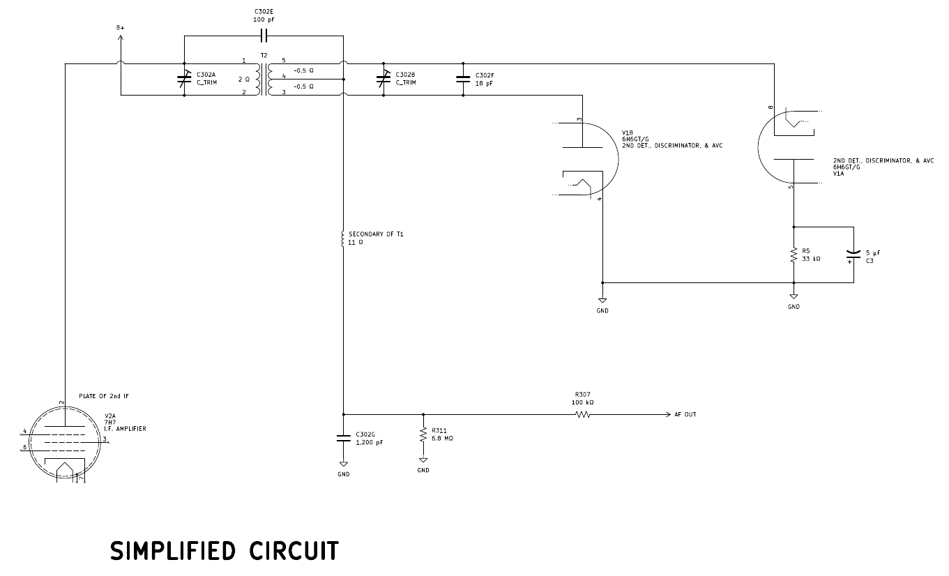
And there we have it. I needed to understand the functionality of the AM and FM detector circuits before I could understand the 32-4074 IF transformer, but now I comprehend the inner workings. I can now select coupled inductors and capacitors which should provide the proper functionality to replace the missing original part.
I will say that I have a bug in Mark Oppat's ear about this. He's been busy lately, but said that next week he can make it to his junkyard to see if he can find a spare 32-4074. But, if not, I am prepared to produce one. I may still do it anyway, just to see how it functions and so that I'll have a backup part.
I have looked, but I could not find a single other model which uses this IF transformer. The only other 1946 model with FM reception, the model 46-1213, was different. I also looked into the 47-1227, because it was supposed to be included in the 1946 model year line-up but was delayed. It had a completely different design as well. I've looked at the 48-482 and the 49-906 as well, but the circuits they implement are quite different.
I'll open this discussion with a screenshot from the first page of the 46-480 service manual, which provides an explanation of the circuit. I'll refer back to this periodically.
In short, there are two factors which make this design very unique. First, there is no switching in any of the IF stages. The only switching between bands occurs just before the first IF stage. Second, AM and FM detection are accomplished with a total of two diodes via a 6H6GT/G tube. Most AM/FM sets at the time used other means, such as a double-diode/triode tube where the two diodes could be utilized for either a Foster-Seeley discriminator or a ratio detector for FM demodulation, and the triode could be used for either plate detection or grid leak detection of AM. Here's a screenshot of the aforementioned AM/FM detection portion of the 46-480.
Notice that the third IF transformer is very strange. For one thing, AM and FM are crammed into a single IF can. It was very common for the first few years for AM and FM detection IF transformers to be combined into one single can. After a few years it became more common to separate AM and FM IF transformers into different cans. But, that said, the AM portion of this IF transformer is strange because it isn't a double-tuned resonant circuit. Pictured below is what I was expecting, one screenshot taken from the Philco model 49-906 schematic (because I also happen to have restored one of these) and the next from vintage-radio.com (specifically, https://www.vintage-radio.com/repair-res...tages.html)
What I am trying to point out is that most AM/FM sets will stack two double-tuned resonant circuits, one for AM and another for FM (be it in one can or in separate cans). AM will be closest to the plate of the IF amplifier tubes, and FM will be closer to the B+ voltage source. I have spent the week trying to comprehend the 46-480's circuit, but here is a summary of what I have come to understand. I will split this into a summary of AM detection and a summary of FM detection. In AM operation, we have the following circuit.
Right away I noticed that this is different from a "textbook" envelope detector circuit, seen in the below excerpt from one of my college textbooks (page 247 of "Introduction to Communication Systems", Third Edition by Ferrel G. Stremler).
The circuit in the 46-480 is different, because the diode is not part of the signal through-path. It instead acts as a pull-down switch. I finally found such an arrangement on page 168 of "Old Time Radios!: Restoration and Repair", seen below.
Having read up on the theory of this particular detector, I could return to analyzing the 46-480 circuit. Essentially, we have a diode half-wave detection of AM, with AVC feedback. As I have already mentioned, you will notice that the primary and secondary windings of T1 do not have capacitors connected in parallel to create resonant circuits. I was baffled for the longest time, but I now understand that it is because the secondary winding also functions as the RF choke coil for the FM circuit; if a capacitor were connected in parallel, it would disturb FM functionality. Thus, in lieu of parallel LC circuits on primary and secondary, capacitors C302C and C302D are inserted as "overcoupling" capacitors. C302D is a trimmer capacitor, so that the circuit can be tuned to couple at precisely the AM IF frequency of 455 kHz, while decoupling at the higher FM frequencies.
A couple of other things happen in AM operation. First, the diode between pins 3 and 4 of the 6H6GT/G is biased to cutoff (confirmed by reading the "General Information on Model 46-480" section on the last page of the attached service manual for this radio). This is accomplished by opening the plate connection to ground, instead forcing the plate to connect to ground through parallel resistance and capacitance. Second, R309 (27 kΩ) is connected to ground. R309 connects between the audio frequency output and ground. When it is grounded on one side in AM operation, it is essentially connected in parallel to R311 (6.8 MΩ), reducing the output resistance to just shy of 27 kΩ (confirmed in the circuit description from the first screenshot). Third, T2 features primary and secondary capacitors connected in parallel--these resonant circuits are not selected to resonate at 455 kHz, and are thus negligible to AM operation. I should also note that there is a small capacitor connected across the detection diode. After some research, I learned that this was often done for diode detectors with common cathodes because the diode is used as a pull-down switch and is thus subject to rapid fluctuations in capacitance compared to envelope detector circuits where the cathode outputs to a smoothing RC circuit. Below is the simplified circuit, showing only the components necessary for AM operation.
Now on to FM operation. Here's a screenshot of the FM detector circuit.
I can tell by the opposing diodes that this is a ratio detector circuit. But it's not quite the textbook version of a ratio detector. Again referencing "Introduction to Communication Systems", Third Edition, here's a picture of page 331 showing the typical ratio detector.
Notice that, to the right of the diodes, there are two capacitors connected in series with a center tap connecting to the output of the RF choke. These series capacitors are connected in parallel with the "very large" capacitor. They provide a sort of ratio, or voltage divider, allowing the voltage of the demodulated output to be a ratio of the total voltage across the "very large" capacitor. When analyzing the ratio detector circuit in the 46-480, I notice that there is no voltage divider created with two capacitors. There is only the single, "very large" capacitor (C314, 5 µF). Furthermore, there are also not two resistors connected in series between the two diodes; there is only a single resistor (R310, 33 kΩ). There are some variants of the ratio detector which have only one resistor. The only difference in functionality is that the reference voltage cannot be centered. In the case of the 46-480, the reference voltage is ground. But the lack of two series capacitors, connected in parallel to the "very large" capacitor really had me stumped.
Enter a 1951 copy of a Philco service manual (attached to this thread and screenshot below this paragraph). It detailed a few variations Philco used of the Foster-Seeley discriminator and the ratio detector, and actually included this exact arrangement. The ratio detector circuit can still function if the output voltage of the RF choke is solidly referenced to the cathode of the diode with the grounded cathode via a resistor and capacitor. And, what would you know, the 46-480 does exactly this (C302G, 1,200 pF and R311, 6.8 MΩ)!
Now that I established what variant of the ratio detector circuit was being used, it was time to think about how the IF transformer came into play. The primary and secondary windings of T2 each feature a capacitor connected in parralel to create a double-tuned resonant circuit. Contrary to the AM transformer, the FM transformer can be arranged this way because the windings of T2 have no function to AM detection. From there, the ratio detector outputs a signal into the RF choke (Secondary winding of T1). Below is the simplified circuit, reduced to showing only the components necessary for FM.
And there we have it. I needed to understand the functionality of the AM and FM detector circuits before I could understand the 32-4074 IF transformer, but now I comprehend the inner workings. I can now select coupled inductors and capacitors which should provide the proper functionality to replace the missing original part.
I will say that I have a bug in Mark Oppat's ear about this. He's been busy lately, but said that next week he can make it to his junkyard to see if he can find a spare 32-4074. But, if not, I am prepared to produce one. I may still do it anyway, just to see how it functions and so that I'll have a backup part.
Joseph
Philco 46-480
Philco 49-906


![[-] [-]](https://philcoradio.com/phorum/images/bootbb/collapse.png)


