02-16-2025, 10:36 AM
Yesterday's antics aside, here is an update on everything I've accomplished on the 46-480 this week.
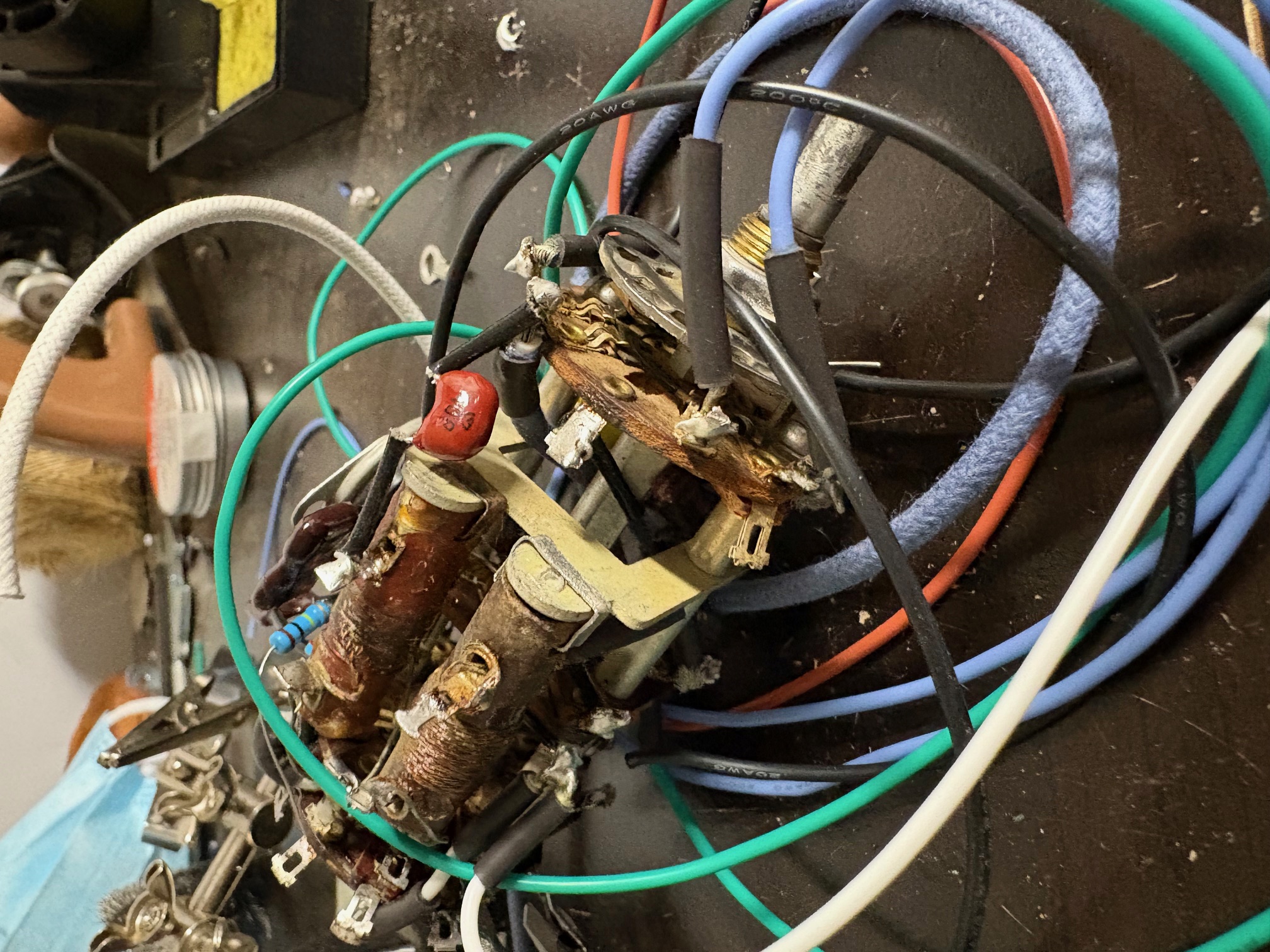
I've got all of the parts in hand now, save for the third IF transformer. I chose to start out with the RF chassis. Recall that the wafer switch assembly was a devilish construction. I chose to get that out of the way first. Here's a photo of it during assembly.
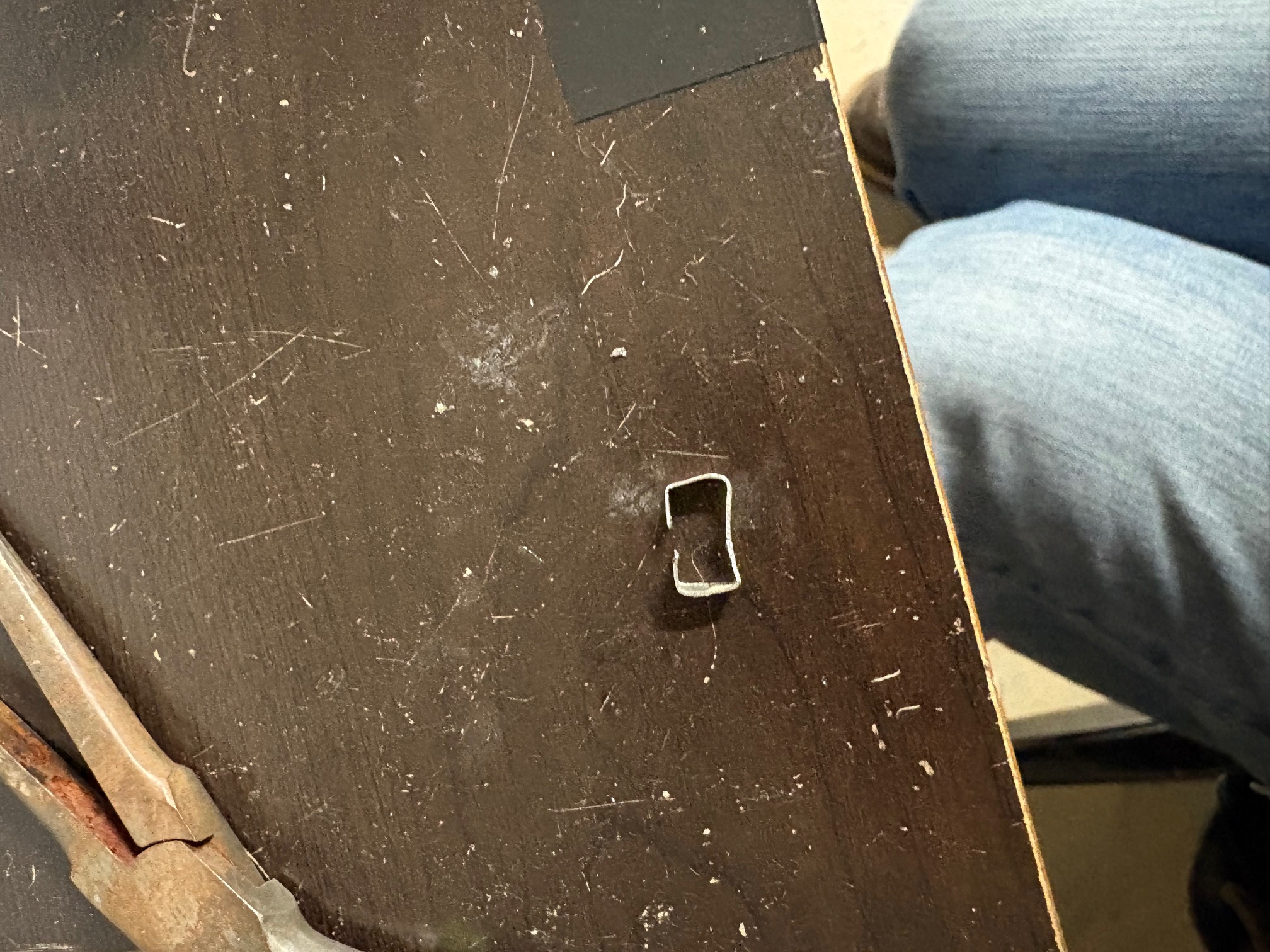
One thing I needed to do was to make a retaining clip for one of those two inductors. It had been missing a clip, and was just held in place by wiring. It was doing just fine like that, but I'm not here to cut corners! I made one out of an empty Altoids tin (I save these for literally everything).

The 7F8 socket and the assembly with C404A/B/C are entirely inaccessible with the wafer switch installed into the chassis, so I had to think very carefully about reassembly. I decided that I would install the components which connect the 7F8 socket to the various connections on the wafer switch, and then I soldered the tube socket to this assembly. I continuously kept trying to fit the assembly into place to make sure that the 7F8 socket would line up perfectly with its cutout on the chassis based on the lengths of the leads I installed on the components. I then decided to install wiring which was just barely long enough to solder to the connections on C404A/B/C with the wafer switch assembly held in place and tilted up just a bit for access. With all of these connections made, I could finally bolt the wafer switch into the RF chassis and could also rivet the 7F8 socket to the chassis.
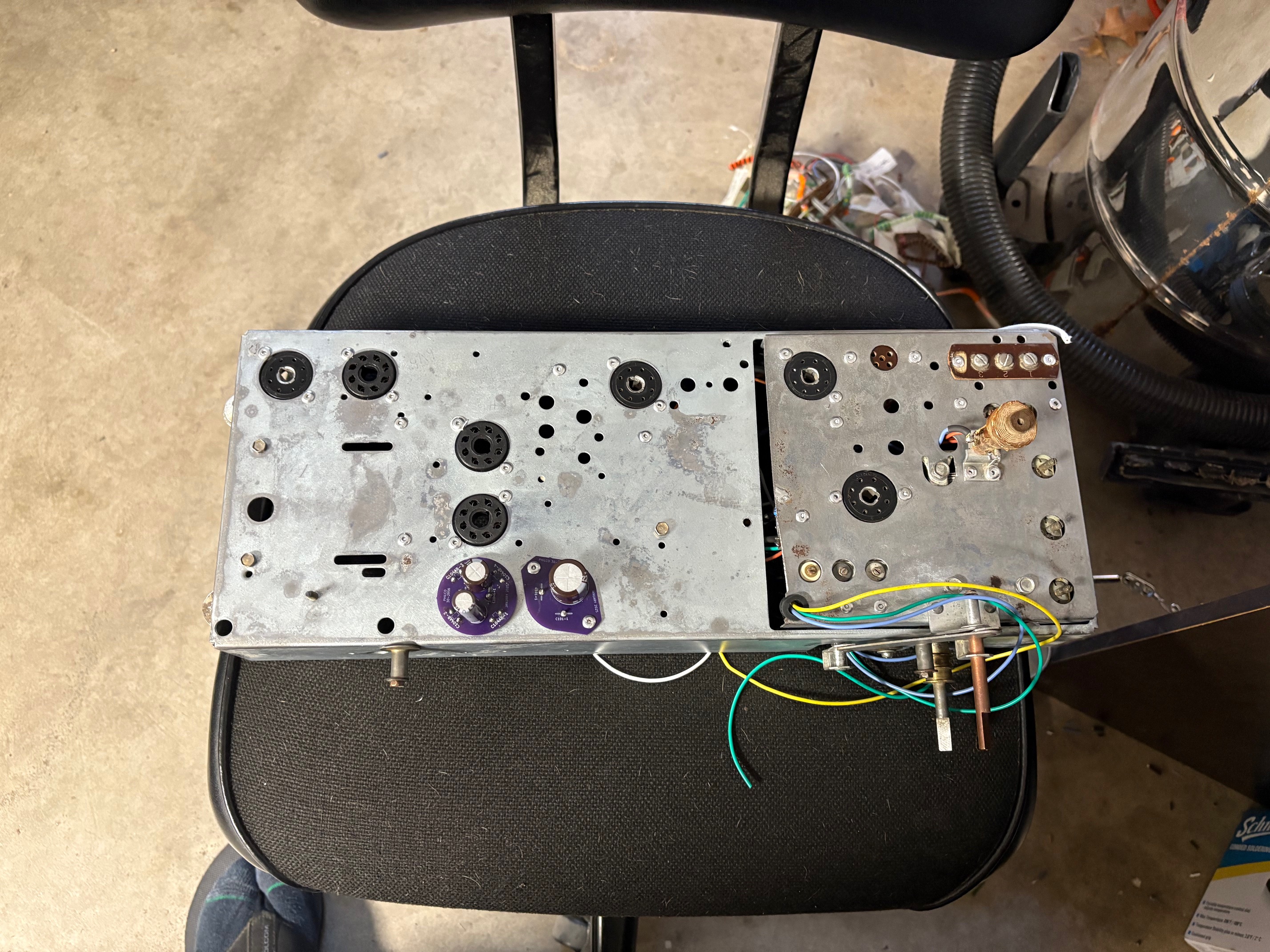
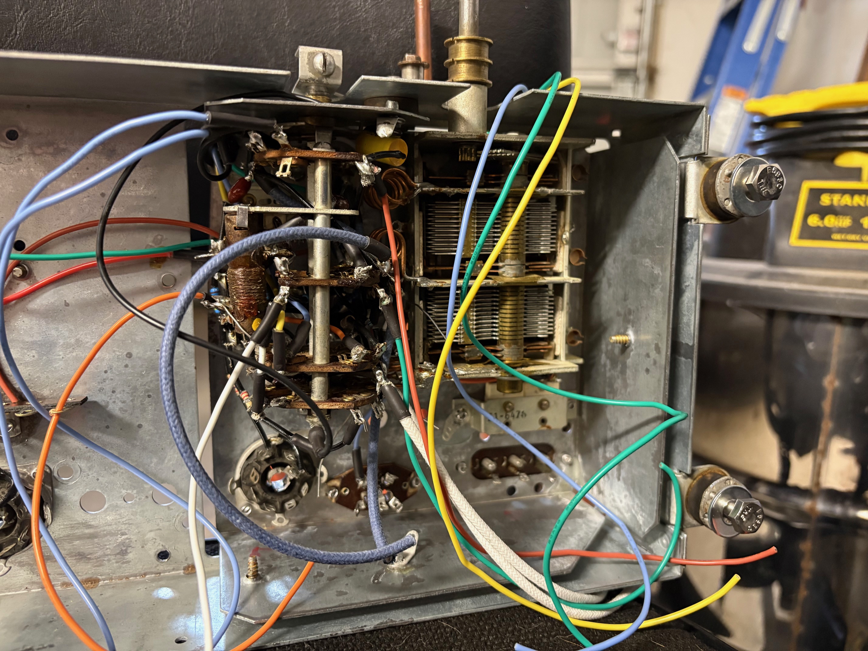
I've already begun grafting all of the wires coming out of this assembly into the rest of the radio, but today I should have time to finish that. I'm about done with the RF section of the circuit. Next I'll do the IF section, then the AF section, and finally the power supply.
I've got a printout of my schematic which I have pinned to the wall above my workstation. I mark it off as I install components.
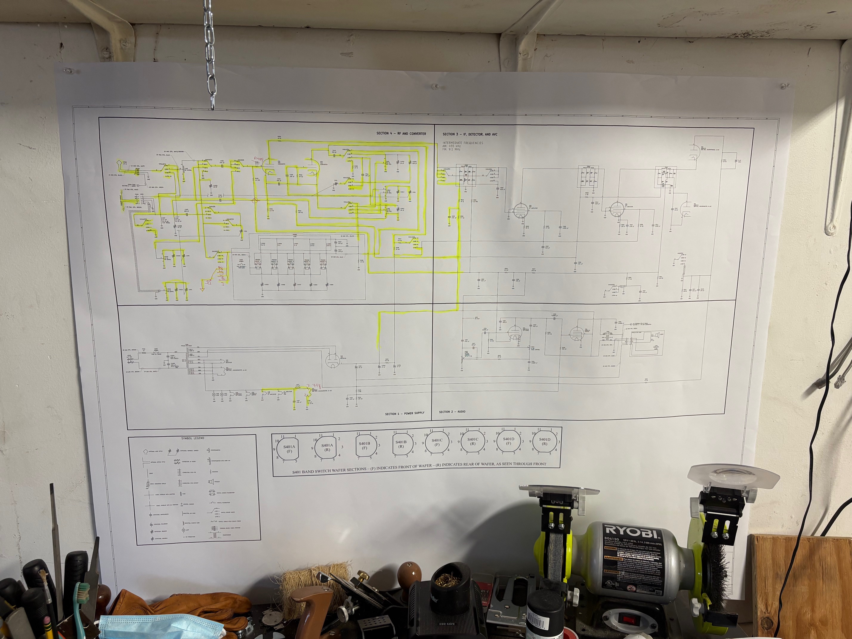
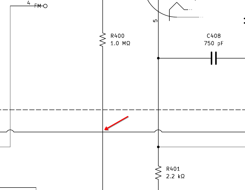
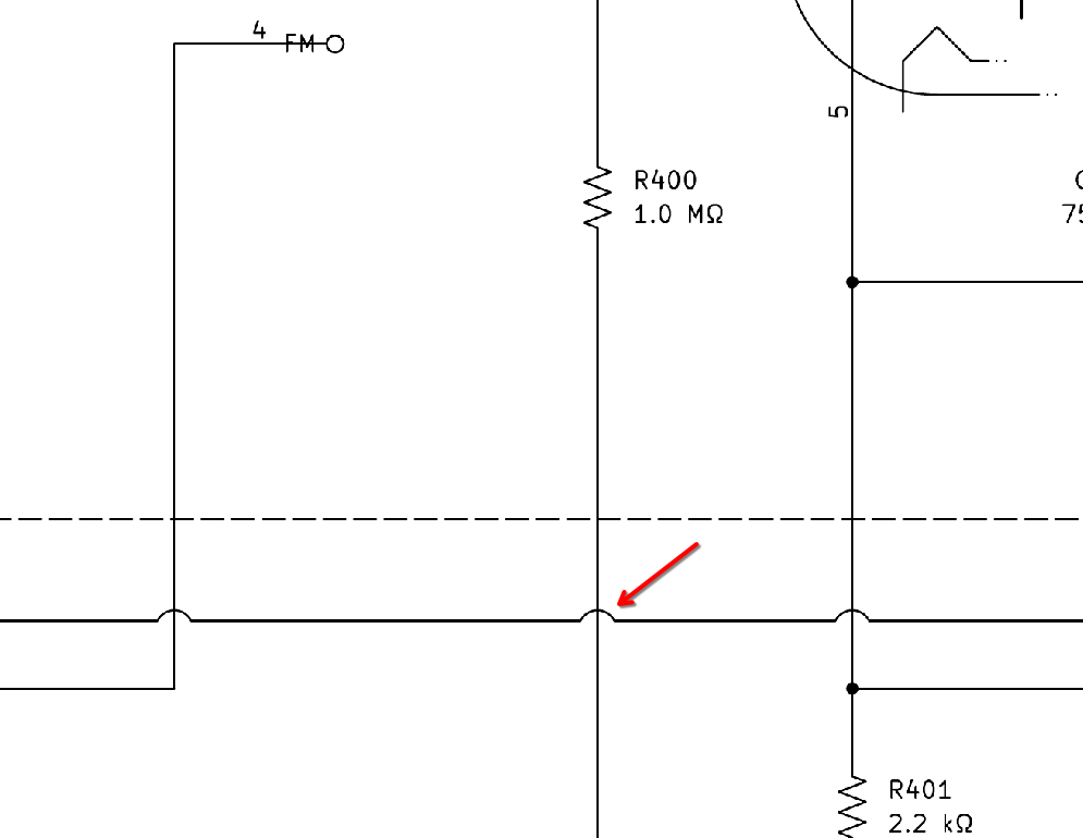
I've realized as I go along that there were a few minor mistakes. First, I realized that I had a crossing of two wires which I had not marked with a dot to indicate a node. I referred back to the original Philco schematic and concurred that there is not a node at that point. So I added a "jump" symbol to indicate that one wire crosses over the other without creating a node.
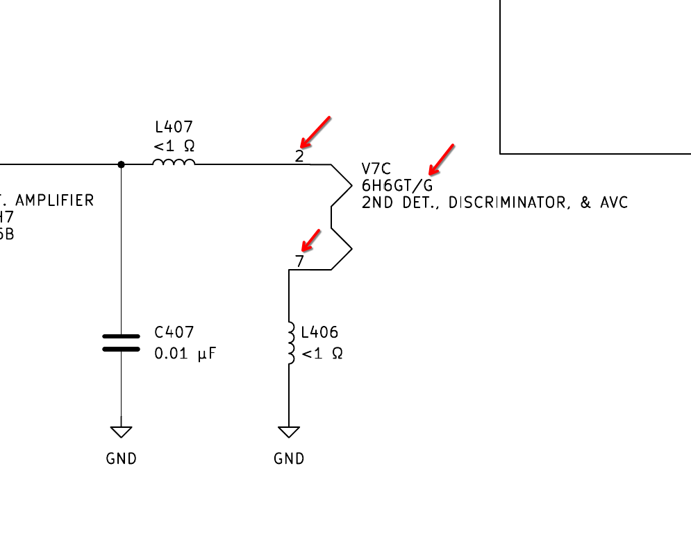
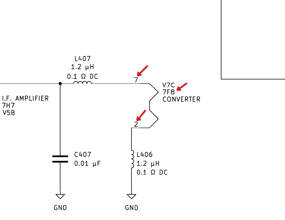
Second, I realized that I had mislabeled the 7F8 heating filament, and had pins 2 and 7 reversed. I caught the reversed pin numbers when looking back at one of my sketches of the wire traces, and consequently noticed the wrong name when I then looked at my schematic.
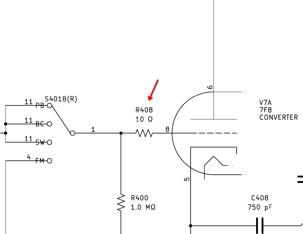
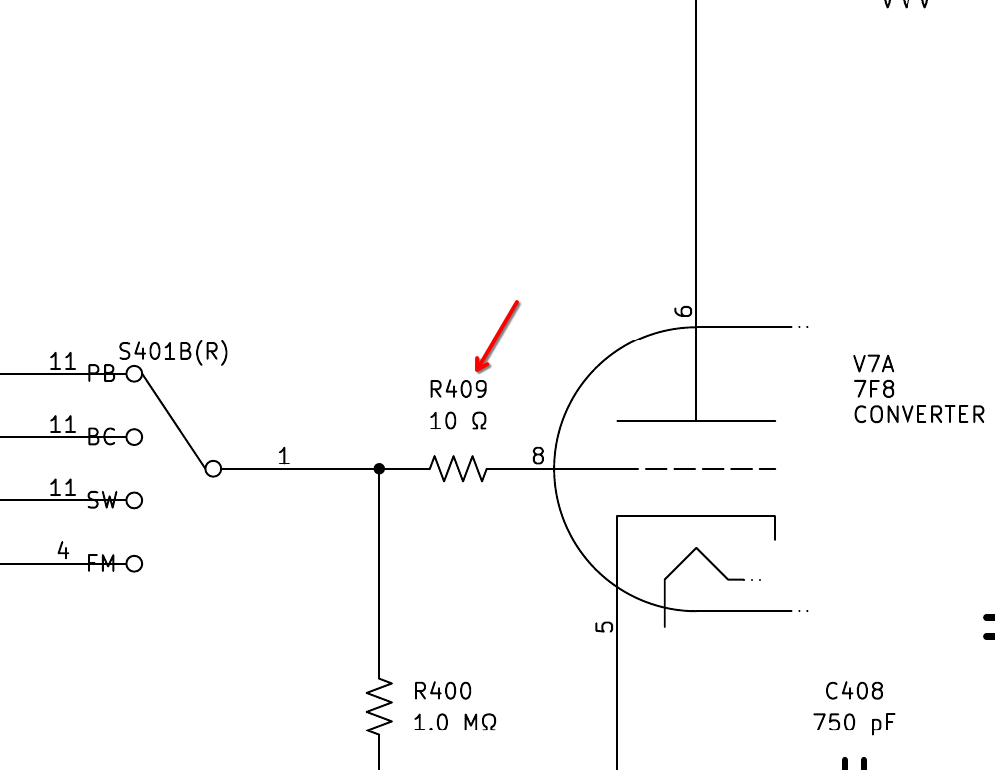
Third, I realized that my schematic had two different resistors labeled R408. Recall back to one of the earliest posts I made in this thread. The complete Philco schematic was missing a grid resistor connecting to pin 8 of the 7F8, whereas the enlarged Section 4 portion of the schematic showed one. The enlarged Section 4 schematic properly calls this resistor R409. I am not sure where I found a reference to it being called R408, but there is already an R408.
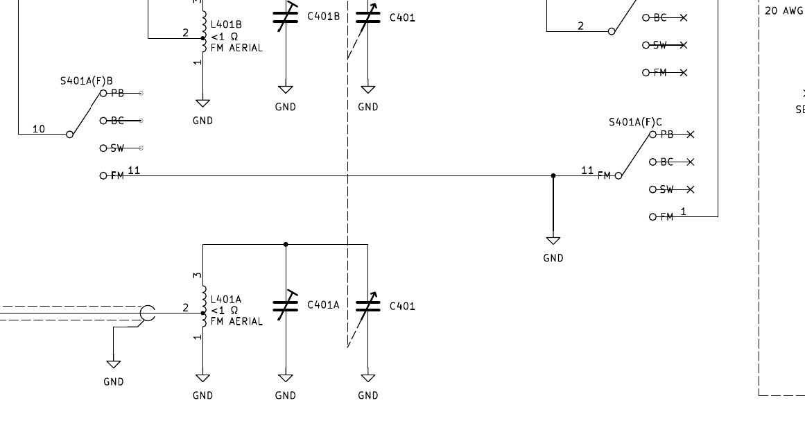
Fourth and final, this was a good one. The original Philco schematic lacked this detail, but the revision notes captured it. I also had depicted it in a sketch of the wire traces while I was disassembling the radio. Essentially, a production change was made to ground pin 1 of S401A(F), so as to ground the push-button trimmer capacitors while in FM mode to prevent oscillation. They accomplished this by creating a hard ground connection at pin 11, and the wafer switch rotor connects pins 11 and 1 while in the FM position. I've decided to add this detail to my schematic, even if the original schematic lacks it. Pin 11 acts as a pole in this application, but also as a throw for another circuit. Hence why you'll see it twice here. I don't like to show it on two different instances of the same switch, but Philco did that in several places on this very schematic so I kept the same styling.
I've made these corrections to the Rev 0 and the Rev 1 PDF, since they are applicable to both. I've gone ahead and re-uploaded both here.
I've got all of the parts in hand now, save for the third IF transformer. I chose to start out with the RF chassis. Recall that the wafer switch assembly was a devilish construction. I chose to get that out of the way first. Here's a photo of it during assembly.
One thing I needed to do was to make a retaining clip for one of those two inductors. It had been missing a clip, and was just held in place by wiring. It was doing just fine like that, but I'm not here to cut corners! I made one out of an empty Altoids tin (I save these for literally everything).
The 7F8 socket and the assembly with C404A/B/C are entirely inaccessible with the wafer switch installed into the chassis, so I had to think very carefully about reassembly. I decided that I would install the components which connect the 7F8 socket to the various connections on the wafer switch, and then I soldered the tube socket to this assembly. I continuously kept trying to fit the assembly into place to make sure that the 7F8 socket would line up perfectly with its cutout on the chassis based on the lengths of the leads I installed on the components. I then decided to install wiring which was just barely long enough to solder to the connections on C404A/B/C with the wafer switch assembly held in place and tilted up just a bit for access. With all of these connections made, I could finally bolt the wafer switch into the RF chassis and could also rivet the 7F8 socket to the chassis.
I've already begun grafting all of the wires coming out of this assembly into the rest of the radio, but today I should have time to finish that. I'm about done with the RF section of the circuit. Next I'll do the IF section, then the AF section, and finally the power supply.
I've got a printout of my schematic which I have pinned to the wall above my workstation. I mark it off as I install components.
I've realized as I go along that there were a few minor mistakes. First, I realized that I had a crossing of two wires which I had not marked with a dot to indicate a node. I referred back to the original Philco schematic and concurred that there is not a node at that point. So I added a "jump" symbol to indicate that one wire crosses over the other without creating a node.
Second, I realized that I had mislabeled the 7F8 heating filament, and had pins 2 and 7 reversed. I caught the reversed pin numbers when looking back at one of my sketches of the wire traces, and consequently noticed the wrong name when I then looked at my schematic.
Third, I realized that my schematic had two different resistors labeled R408. Recall back to one of the earliest posts I made in this thread. The complete Philco schematic was missing a grid resistor connecting to pin 8 of the 7F8, whereas the enlarged Section 4 portion of the schematic showed one. The enlarged Section 4 schematic properly calls this resistor R409. I am not sure where I found a reference to it being called R408, but there is already an R408.
Fourth and final, this was a good one. The original Philco schematic lacked this detail, but the revision notes captured it. I also had depicted it in a sketch of the wire traces while I was disassembling the radio. Essentially, a production change was made to ground pin 1 of S401A(F), so as to ground the push-button trimmer capacitors while in FM mode to prevent oscillation. They accomplished this by creating a hard ground connection at pin 11, and the wafer switch rotor connects pins 11 and 1 while in the FM position. I've decided to add this detail to my schematic, even if the original schematic lacks it. Pin 11 acts as a pole in this application, but also as a throw for another circuit. Hence why you'll see it twice here. I don't like to show it on two different instances of the same switch, but Philco did that in several places on this very schematic so I kept the same styling.
I've made these corrections to the Rev 0 and the Rev 1 PDF, since they are applicable to both. I've gone ahead and re-uploaded both here.
Joseph
Philco 46-480
Philco 49-906


![[-] [-]](https://philcoradio.com/phorum/images/bootbb/collapse.png)


