04-05-2025, 12:41 PM
I am almost finished with this restoration. All which remains is the power transformer. I cleaned it up some time ago, but never did purchase the sleeves to cover the cracked insulation of the high side wires. I had tested it using normal heat shrink (rated for 600V), but the high side is 640V nominal. Yesterday morning I ordered some 11 AWG fiberglass spaghetti style sleeving, rated up to 7kV, from Antique Electronic Supply. It should arrive on Wednesday. I had two choices--either 20 AWG sleeving or 11 AWG. I have some of the 20 AWG on hand, but it's too small. Even if I were to strip the original insulation off of the wires, I think they are 18 AWG. My thought is to leave the insulation intact, and cover it with the 11 AWG sleeve. Should fit just fine.
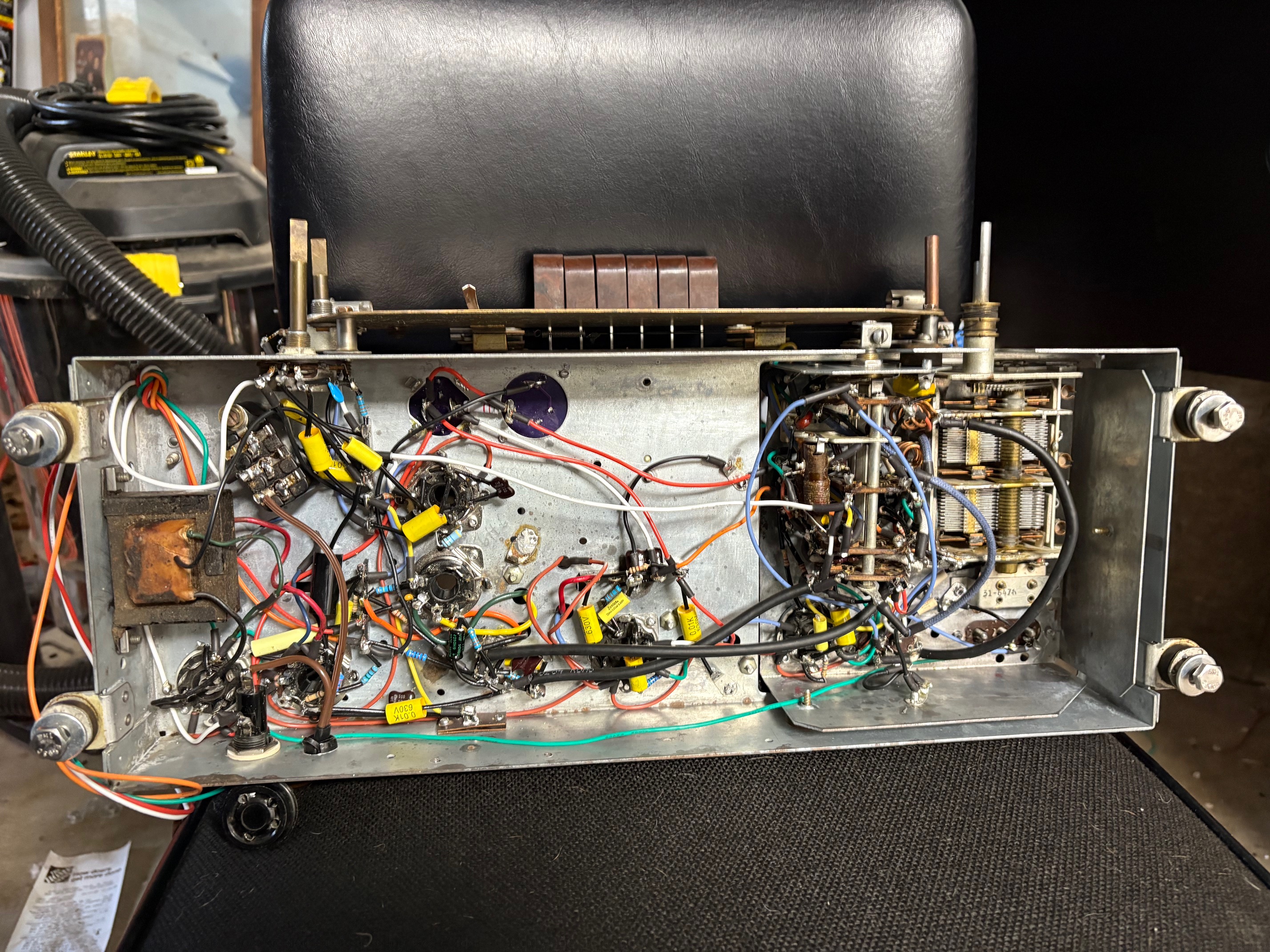
Here's my progress from the last week. I finished the push-button assembly, I wired in the 32-4074 IF transformer I had received from Mark Oppat, and completed the audio output section. I replaced the brittle wires on the cord for the speaker, and installed a new AC cable with a polarized plug. I reworked the power supply to include a 1A fuse on the hot side, moved the on/off switch to the hot side, and moved the X1Y1 line filtering capacitors downstream of the switch so that they are de-energized when the radio is powered off. This is all depicted in the Rev 1 version of my schematic.
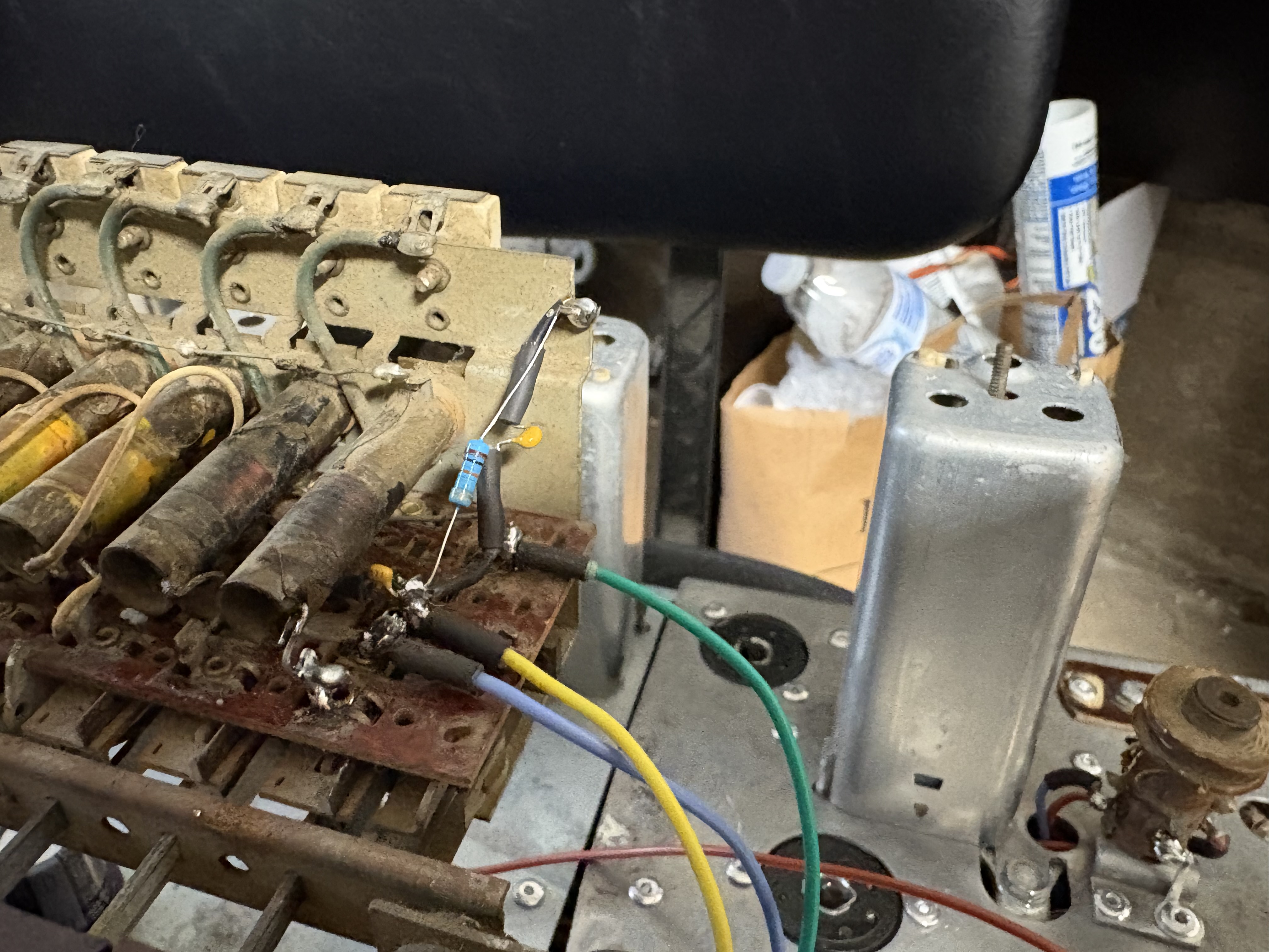
Speaking of the push-button assembly, I discovered some damage to the right-most LC circuit. One of the wires had been severed (probably due to mice chewing on it, based upon the rest of the damage I've seen). I was able to repair it, but left a minor burn mark on the cardboard tube from my soldering iron.

Aside from that, I discovered one minor error on my schematic. When I created the Rev 1 version to depict the changes to the power section and resistance/capacitance substitutions I have made, I did not move a wire type call-out for one of the cables passing from the underside of the chassis to the push-button assembly for the power switch. This error only affects Rev 1, so I've fixed it and reuploaded here.
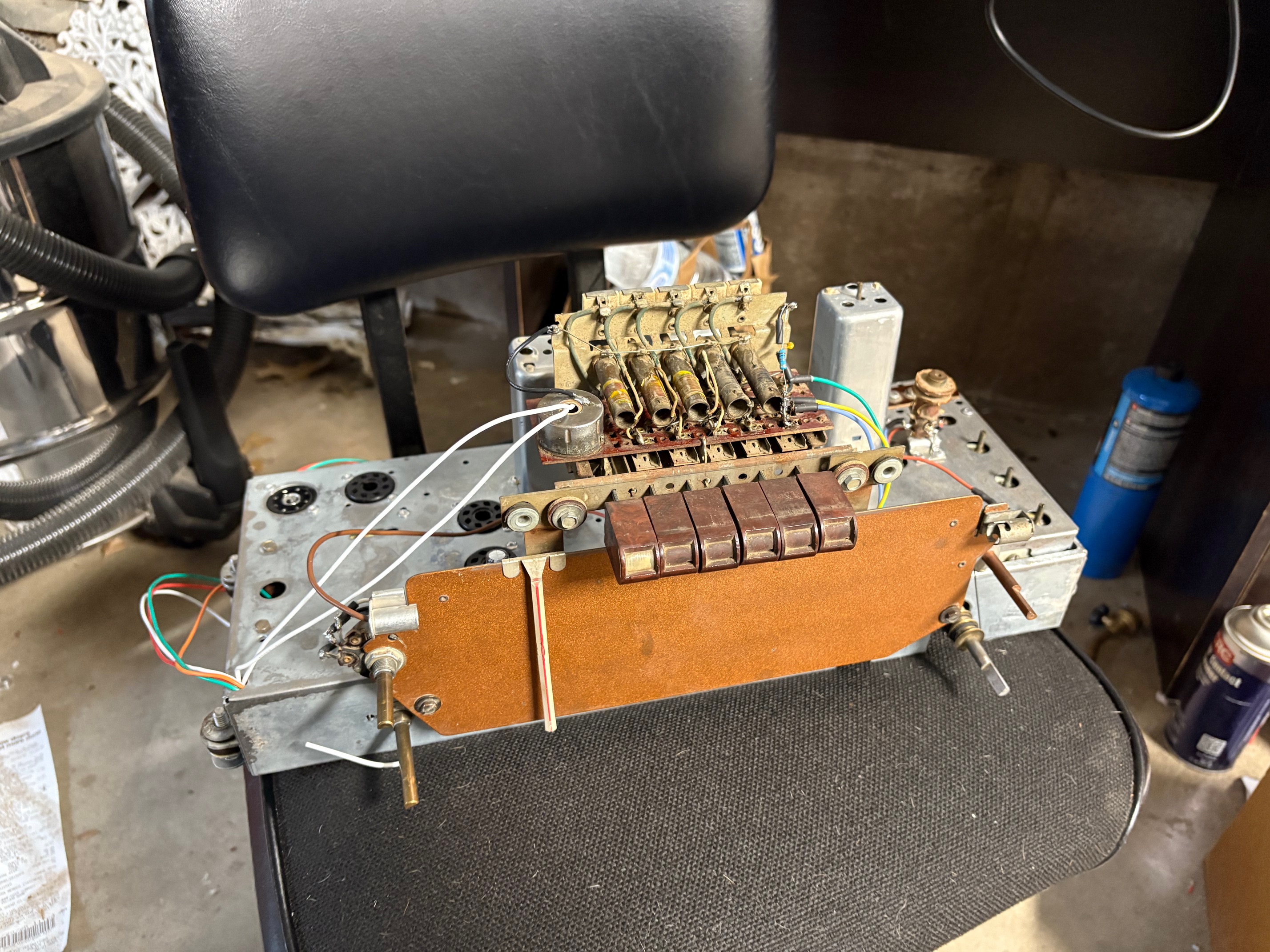
Here's the radio as it looks right now, waiting on the power transformer and the tubes to be inserted.


Here's my progress from the last week. I finished the push-button assembly, I wired in the 32-4074 IF transformer I had received from Mark Oppat, and completed the audio output section. I replaced the brittle wires on the cord for the speaker, and installed a new AC cable with a polarized plug. I reworked the power supply to include a 1A fuse on the hot side, moved the on/off switch to the hot side, and moved the X1Y1 line filtering capacitors downstream of the switch so that they are de-energized when the radio is powered off. This is all depicted in the Rev 1 version of my schematic.
Speaking of the push-button assembly, I discovered some damage to the right-most LC circuit. One of the wires had been severed (probably due to mice chewing on it, based upon the rest of the damage I've seen). I was able to repair it, but left a minor burn mark on the cardboard tube from my soldering iron.
Aside from that, I discovered one minor error on my schematic. When I created the Rev 1 version to depict the changes to the power section and resistance/capacitance substitutions I have made, I did not move a wire type call-out for one of the cables passing from the underside of the chassis to the push-button assembly for the power switch. This error only affects Rev 1, so I've fixed it and reuploaded here.
Here's the radio as it looks right now, waiting on the power transformer and the tubes to be inserted.
Joseph
Philco 46-480
Philco 49-906


![[-] [-]](https://philcoradio.com/phorum/images/bootbb/collapse.png)


