Yesterday, 09:54 AM
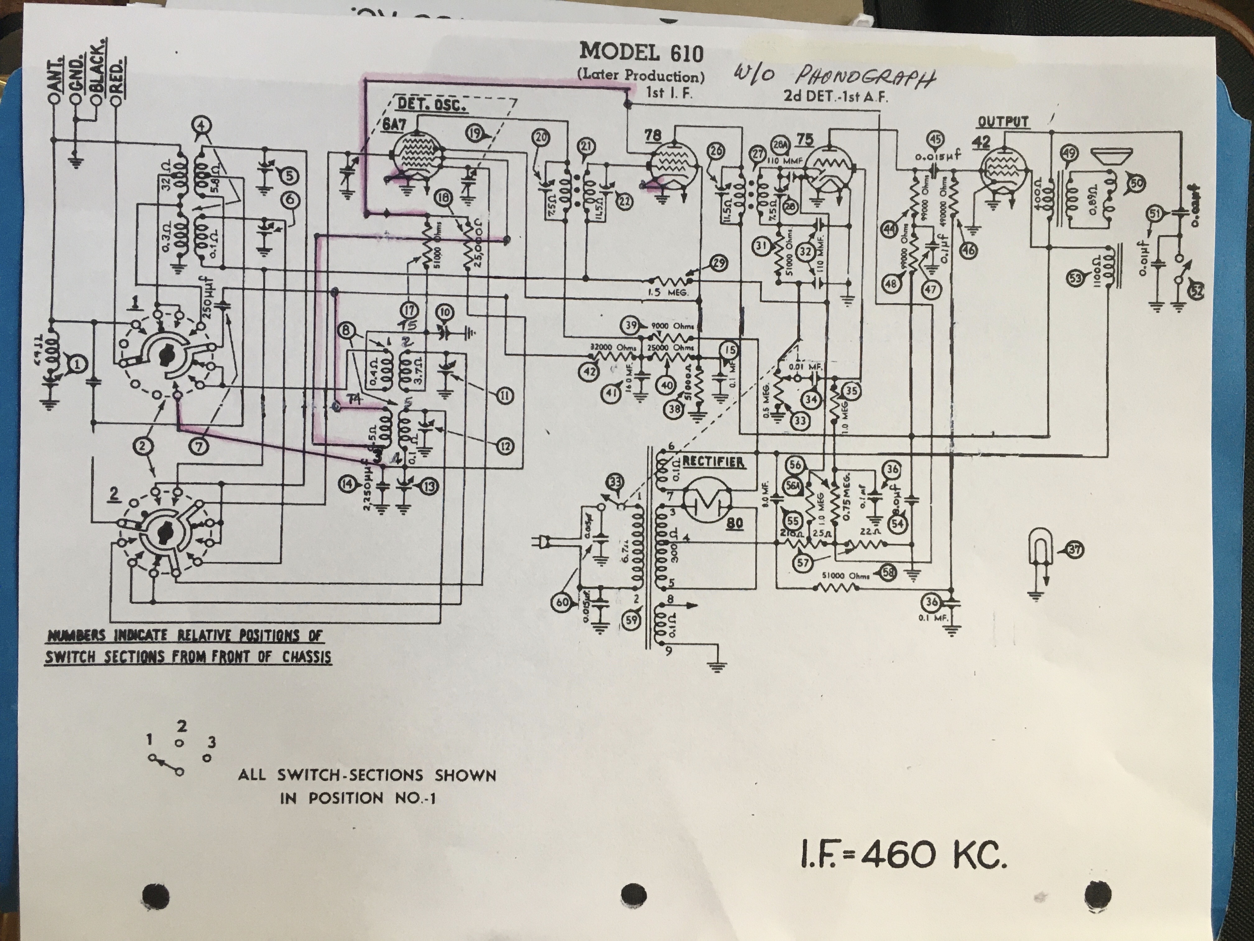
Thank you all for your replies as I will refer to them as I complete my project. My dilema is best captured on the included attachement. I've tried to hi-light in red the deviations from published schematics for a later production 610b. As you can see, the oscillator wiring for the 0.5 ohm primary is wired directly to the 6A7 grid 2 pin on one side and the other side wired between the 250pF cap and 32k resister. Also, one side of the 0.1 phm secondary is wired to bandwidth switch 2. I'm looking for any comments on this arrangement. My plan is to rewire according to published schematics + recorded philco radio service bulletins. Thanks!
.

.


![[-] [-]](https://philcoradio.com/phorum/images/bootbb/collapse.png)


