



01-04-2026, 03:38 PM
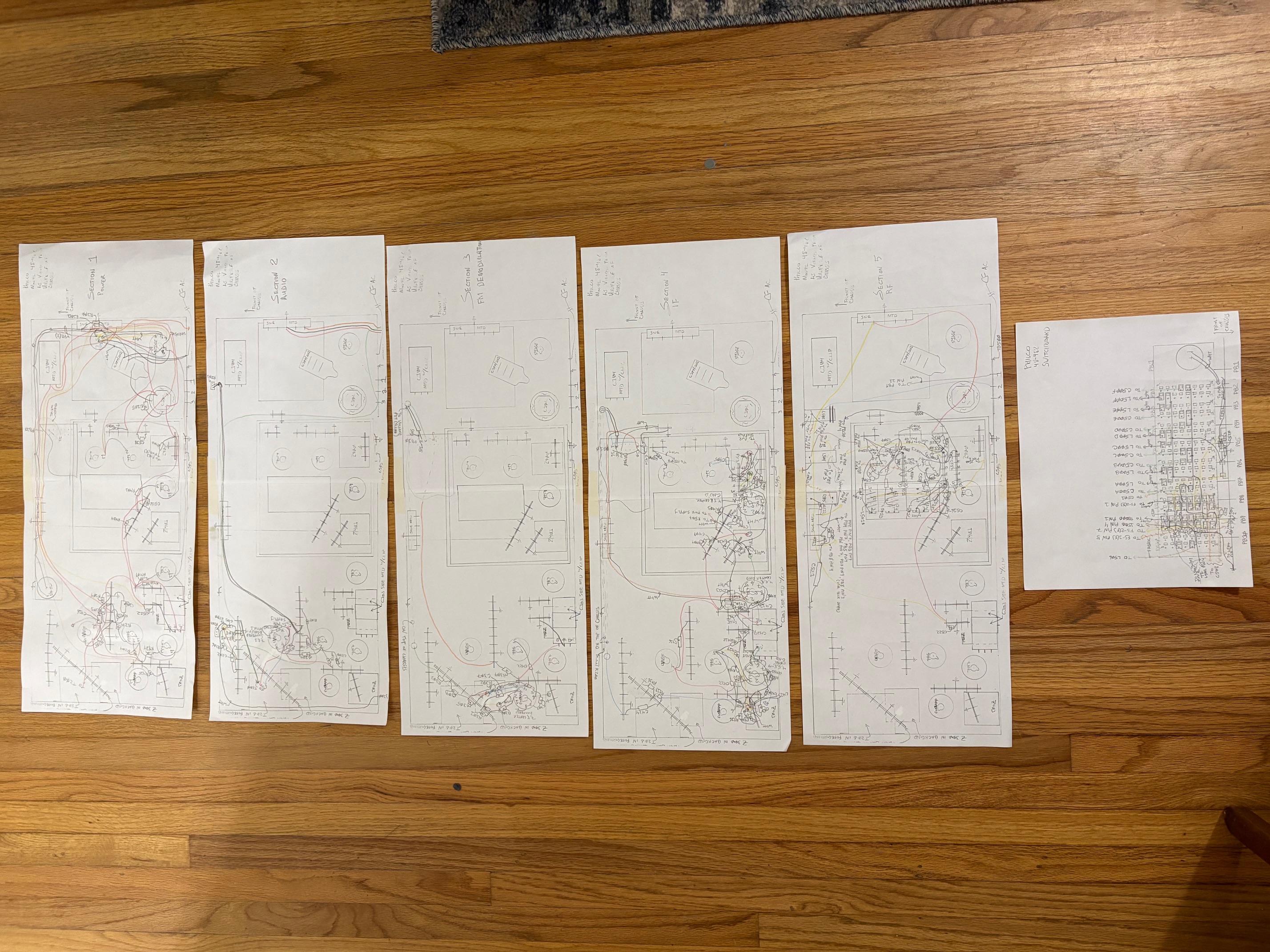
It’s been about three months of on-and-off-again work, but at last I have a schematic put together for the 48-482. I have combed through two complete chassis and compared them against the scanned Philco schematic available from the Philco Libraries. There are five sections to the schematic:
Per my usual process, I drew the underside of the chassis and showed all terminal blocks, tubes, and other major equipment. I then made five copies and drew out all of the wiring for each of the five sections. I also made a drawing of the switch board for the ten push buttons:
Additionally, I checked each resistor and capacitor to verify the values listed in the Philco documentation. Whereas the documentation indicated that capacitors C302, C406, C412, and C418 should be 0.01 uF, I discovered that they were all 0.006 uF in both the chassis I have. The information for C503 was incomplete but I confirmed it to be a 0.01 uF, 600 VDC paper capacitor. Additionally, C511 is a 25 pF Mica capacitor, not 22 pF. So far as resistors are concerned, R406 is listed as being a 3.3 kohm resistor, but I found it to be a 2.2 kohm resistor in both chassis. The listed part number (66-222340) for R505 was one character short. It is a 2.2 kohm resistor as the documentation indicates, but I had to deduce the wattage. The schematic indicates that there are 4.5 V across R505, and thus a 1/2 W resistor will suffice.
One more note about my schematic. The Philco schematic shows all of the push buttons switches, but it inconsistently shows the push buttons as being selected or not selected throughout the schematic. I decided to depict the throws of each SPDT switch consistently as though the OFF button were depressed. All push buttons are interlocked, meaning that no push-button preset nor the AM, SW, nor FM band push buttons can be depressed if the OFF button is pushed. However, I preserved the style of the Philco schematic by indicating which modes correspond to both throws of each SPDT switch.
I have attached the schematic to this thread. It’s a massive and complex schematic, so it’s on an E-sized sheet. But the readability is much better than the original scanned schematic!
- Power Supply
- Audio Frequency
- FM Demodulation
- Intermediate Frequency
- Radio Frequency
Per my usual process, I drew the underside of the chassis and showed all terminal blocks, tubes, and other major equipment. I then made five copies and drew out all of the wiring for each of the five sections. I also made a drawing of the switch board for the ten push buttons:
Additionally, I checked each resistor and capacitor to verify the values listed in the Philco documentation. Whereas the documentation indicated that capacitors C302, C406, C412, and C418 should be 0.01 uF, I discovered that they were all 0.006 uF in both the chassis I have. The information for C503 was incomplete but I confirmed it to be a 0.01 uF, 600 VDC paper capacitor. Additionally, C511 is a 25 pF Mica capacitor, not 22 pF. So far as resistors are concerned, R406 is listed as being a 3.3 kohm resistor, but I found it to be a 2.2 kohm resistor in both chassis. The listed part number (66-222340) for R505 was one character short. It is a 2.2 kohm resistor as the documentation indicates, but I had to deduce the wattage. The schematic indicates that there are 4.5 V across R505, and thus a 1/2 W resistor will suffice.
One more note about my schematic. The Philco schematic shows all of the push buttons switches, but it inconsistently shows the push buttons as being selected or not selected throughout the schematic. I decided to depict the throws of each SPDT switch consistently as though the OFF button were depressed. All push buttons are interlocked, meaning that no push-button preset nor the AM, SW, nor FM band push buttons can be depressed if the OFF button is pushed. However, I preserved the style of the Philco schematic by indicating which modes correspond to both throws of each SPDT switch.
I have attached the schematic to this thread. It’s a massive and complex schematic, so it’s on an E-sized sheet. But the readability is much better than the original scanned schematic!
Joseph
Philco 39-750 EZ
Philco 46-480
Philco 47-1230
Philco 48-482
Philco 49-906




