



02-05-2026, 08:46 AM
Hi SlidesK,
+1 on what Morzh said.
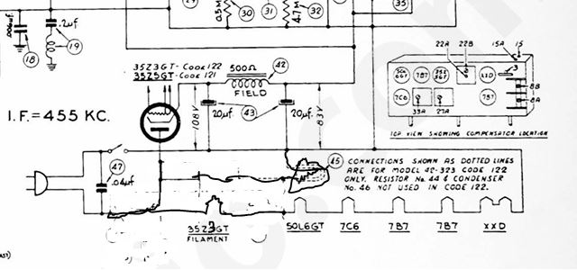
Please note that on the Code 122 version of this set, that there is no indicator bulb tap on a 35Z3, which is your rectifier. Please note that your set uses a 120V indicator lamp. Best place to put it is between the unswitched leg of the power supply (pins 1 and 2 of the 35Z3) and the "load side" of the switch (B-, negative leads of electrolytic caps, a filament pin of the XXD, etc.). In other words, the indicator lamp is NOT part f the filament string. The original was likely a 3 Watt or 7 Watt indicator light with a base similar to that used in nightlights, old school Christmas lights and chandeliers.
Refer to the drawing attached and my horribly drawn indicator lamp. This is the same diagram that I sent to you to troubleshoot the filament wiring. to cut down on heat, you can use an LED version of a C7 bulb. Note that on the published version of the schematic, the dotted lines indicate the indicator lamp for the Code 122 version. The Xs indicate to the Tech to ignore what is between the Xs. Unfortunately, this made the diagram both difficult to read and incorrect (not showing where a 35Z3 filament goes to instead of the 35Z5 filament.
As far as the plate voltage of the 7C6 1st AF stage, verify the resistance of the 470 KOhm resistor and that the 0.01 uF cap is new and good. If this is so, then don't worry. The slightly high B+ voltage will not cause the proportionally much higher B+ on the 1st audio stage.
As to the missing 47K resistor, if it is missing, I don't know if I would worry too much about it. Seems to me that this is the oscillator circuit (The mixer is the right side of the tube), and a 47K resistor is rather low to use as a "grid leak". I would measure between the cathode and grid or between the grid and the negative terminal of the filter caps. If you have a resistance there that is less than 1 MOhm, I wouldn't worry about it. The circuit works.
Hope this helps.
+1 on what Morzh said.
Please note that on the Code 122 version of this set, that there is no indicator bulb tap on a 35Z3, which is your rectifier. Please note that your set uses a 120V indicator lamp. Best place to put it is between the unswitched leg of the power supply (pins 1 and 2 of the 35Z3) and the "load side" of the switch (B-, negative leads of electrolytic caps, a filament pin of the XXD, etc.). In other words, the indicator lamp is NOT part f the filament string. The original was likely a 3 Watt or 7 Watt indicator light with a base similar to that used in nightlights, old school Christmas lights and chandeliers.
Refer to the drawing attached and my horribly drawn indicator lamp. This is the same diagram that I sent to you to troubleshoot the filament wiring. to cut down on heat, you can use an LED version of a C7 bulb. Note that on the published version of the schematic, the dotted lines indicate the indicator lamp for the Code 122 version. The Xs indicate to the Tech to ignore what is between the Xs. Unfortunately, this made the diagram both difficult to read and incorrect (not showing where a 35Z3 filament goes to instead of the 35Z5 filament.
As far as the plate voltage of the 7C6 1st AF stage, verify the resistance of the 470 KOhm resistor and that the 0.01 uF cap is new and good. If this is so, then don't worry. The slightly high B+ voltage will not cause the proportionally much higher B+ on the 1st audio stage.
As to the missing 47K resistor, if it is missing, I don't know if I would worry too much about it. Seems to me that this is the oscillator circuit (The mixer is the right side of the tube), and a 47K resistor is rather low to use as a "grid leak". I would measure between the cathode and grid or between the grid and the negative terminal of the filter caps. If you have a resistance there that is less than 1 MOhm, I wouldn't worry about it. The circuit works.
Hope this helps.
"Do Justly, love Mercy and walk humbly with your God"- Micah 6:8
"Let us begin to do good"- St. Francis
Best Regards,
MrFixr55


