



02-25-2026, 09:31 PM
Hi Jeff,
Refer to the pictorial and the parts list for the radio, found in our Philco Library, a link posted here:
https://philcoradio.com/library/download...20Book.pdf
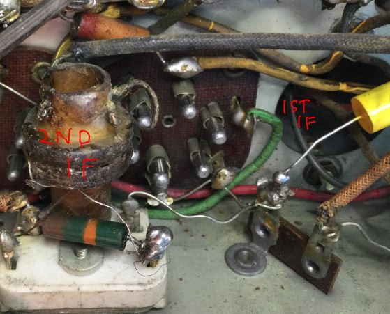
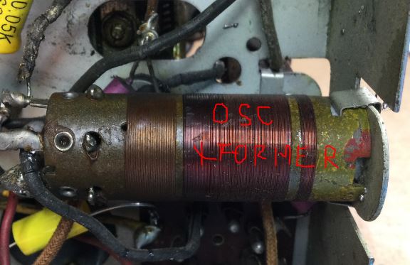
Below are snags of your 2 pics. I identified the transformers based on the pictorial in the above service document:
The exposed coil in the pic below is the 2nd IF transformer. The one in the can is the 1st IF transformer:
The coil in the pic below is the oscillator transformer:
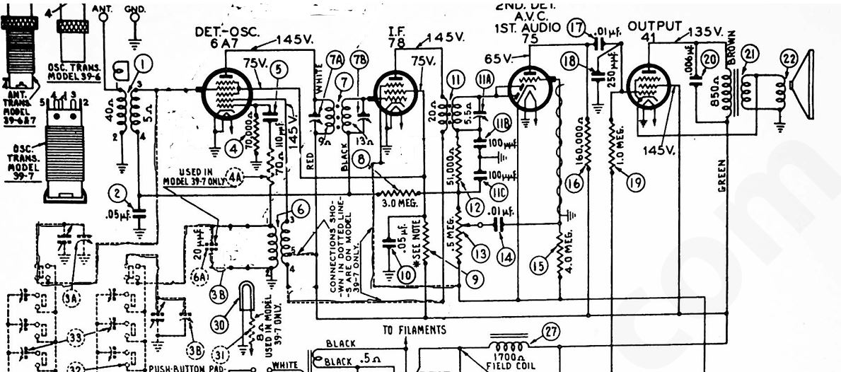
The following tests may help you. Do use the RCA Receiving Tube Manual for the pinouts (Tube socket wiring) for the 75, 78 and 6A7 tubes as your problem now lies in these stages. The diagram below has been modified to show most of the connections for the 39-7 and eliminate the connections for the 39-6. Ensure that your work is true to the diagram other than you can leave the pushbuttons out of the circuit and connect tuning cap 3 (A and B) per the diagram.
Start out by disconnecting power and set your DVM to Ohms, auto ranging.
Correct any defects found, and you will likely restore operation of the radio.
Good luck!
Refer to the pictorial and the parts list for the radio, found in our Philco Library, a link posted here:
https://philcoradio.com/library/download...20Book.pdf
Below are snags of your 2 pics. I identified the transformers based on the pictorial in the above service document:
The exposed coil in the pic below is the 2nd IF transformer. The one in the can is the 1st IF transformer:
The coil in the pic below is the oscillator transformer:
The following tests may help you. Do use the RCA Receiving Tube Manual for the pinouts (Tube socket wiring) for the 75, 78 and 6A7 tubes as your problem now lies in these stages. The diagram below has been modified to show most of the connections for the 39-7 and eliminate the connections for the 39-6. Ensure that your work is true to the diagram other than you can leave the pushbuttons out of the circuit and connect tuning cap 3 (A and B) per the diagram.
Start out by disconnecting power and set your DVM to Ohms, auto ranging.
- Measure between the diode plates (Pins 3 and 4 tied together) of the 75 Detector / 1st AF amp and the junction of the secondary of the 2nd IF transformer #11 and 51 KOhm Resistor #12, across 1Trimmer cap 11A. You should read about 5 Ohm. This validates the secondary of the second IF transformer.
- Next, measure between the plate (#Pin 2) of the 78 IF transformer and the 6A7 Mixer Plate (Pin 2). You should get a reading close to 15 ohms. This confirms connection from the 78 Plate, through the 2nd IF primary, Pins 4 and 5 of the Oscillator coil, the 1st IF Primary and the Plate of the 6A7 Convertor.
- Next, measure between the Plate (pin 2) of the 6A7 and the "Grid Plate" (Oscillator Plate, Pin 4) of the 6A7 Convertor tube. There should be about 6 Ohm. This again confirms the 1st IF transformer primary abd confirms the continuity of the Oscillator Coil between pins 3 and 5.
- Next, measure between chassis ground and the stator of the oscillator section of the tuning cap (usually the section closest to the front of the tuning cap and the shaft. There should be a reading of somewhere between 5 and 40 Ohms (resistance is not on the diagram). This confirms continuity of the coil and connection to the oscillator section of the tuning cap.
- Next, measure between the grid cap of the 6A7 and the grid cap of the 78 IF tube. This confirms continuity of the secondary of the antenna coiland the secondary of the 1st IF transformer. Resistance reading should be about 18 Ohms. Next measure between the RF stator of the tuning capacitor (the rear section; the grid cap of the 6A7 connects to it and the grid cap of the 78 IF tube. This confirms connection to the tuning cap.
- Next, verify continuity between the frame of the tuning cap and the rotor of the tuning cap and between the frame of the tuning cap and chassis ground. These readings should be Zero Ohms.
- Next, verify continuity between the antenna and ground connections. This should be about 40 Ohms.
- Finally, verify that you replaced the 0.05uF cap between chassis ground, pin 4 of the Antenna transformer and the 1st IF secondary (this is the AVC Line)
Correct any defects found, and you will likely restore operation of the radio.
Good luck!
"Do Justly, love Mercy and walk humbly with your God"- Micah 6:8
"Let us begin to do good"- St. Francis
Best Regards,
MrFixr55




