



03-29-2026, 12:23 AM
Thank you for the responses received so far. I've managed to free up the tuning module from the main chassis for some extra elbow room/compartmentalization of repairs. Lots of pictures and notes taken so far for reassembly.
A new question as I prepare to order some components. I went through and tested the resistors (all except one - see notes below) and none test at the ohms the parts list specifies (no surprise I'm sure). Results are below, a couple are somewhat close to spec, others way off. I've read that radios of this era were built to tolerate a variation from spec of up to 20% because of the quality/reliability of the components of the day; also that it's safer to have a little higher than rated than a little under. I'm inclined to replace them all given some of these readings, and given that I hope to never have to take this apart again. Thoughts?
Schematic No - Intended Rating - Measured value
6 - 61,000 ohms - 57,000 ohms (under by 6.6%)
16 - 51,000 ohms - 89,000 ohms (over by 74.5%)
17 - 20,000 ohms - 23,700 ohms (over by 18.5%)
19 - 10,000 ohms - 11,960 ohms (over by 19.6%)
29 - 70,000 ohms - 79,000 ohms (over by 12.9%)
30 - 32,000 ohms - 37,400 ohms (over by 16.9%)
33 - 1,000 ohms - 853 ohms (under by 14.7%)
34 - 400 ohms - 735 ohms (over by 83.8%) - this is the Bakelite, wraps around a paper capacitor that also needs replacing, any special guidance on this one?
39 - 51,000 ohms - 55,100 ohms (over by 8.0%) - might be safe to keep in place?
41 - 490,000 ohms - 500,000 ohms (over by 2.0%) - probably safe to keep in place?
44 - 1,000,000 ohms - 1,500,000 ohms (over by 50.0%)
46 - 51,000 ohms - 49,700 ohms (under by 2.5%)
50 - 1,000,000 ohms - 1,140,000 ohms (over by 14.0%)
53 - 1,000,000 ohms - 1,130,000 ohms (over by 13.0%)
55 - 490,000 ohms - 480,000 ohms (under by 2.0%)
58 - 1,000,000 ohms - 980,000 ohms (under by 2.0%)
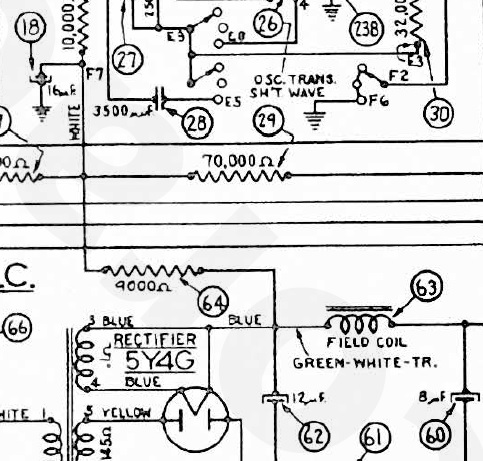
64 - 9,000 ohms - could not find in chassis; I see it looks to be between electrolytics #62 and #18 electrically, and connected to a bunch of other things, but it's not on the diagram of the chassis; excerpt of schematic below
Aside from those questions, some follow up to the feedback I've received:
"All paper and electrolytic caps should go, the mica caps stay unless damaged." - Heard and on-board. Electrolytics already replaced, paper will all go for sure, micas can stay. What about the two "Semi-fixed" ones that are inside the tuning circuit? Which category do they fall under? Like the micas, their ratings are in pfd instead of mfd.
#1 - My question about the 8318-SU before was based in the fact that I didn't know the underlying technology inside the bakelite housing(s). Are they effectively equivalent to the paper caps in that sense? I see a lot of talk of "re-stuffing" so I presume they are most often included in re-capping. Follow up, now that I realize it however, I believe the capacitors that replace the electrolytics are polarized; the rest that we're dealing with should not be polarized, correct? So directionality in installation shouldn't matter going forward?
#3 - Expanding on before, I've added a photo below to show the power/tone control. The two power wires go to the lugs at the back (black) part of the pot; at least two lugs appear further in stemming from the metallic section nearer the chassis front. The little wire dangling up and over, floating to nowhere comes off of lug 3 on the 8318-SU which as I mentioned before (on the schematic) looks like it's supposed to connect with part of this pot, but not sure if that's right and if so, which lug to connect to.
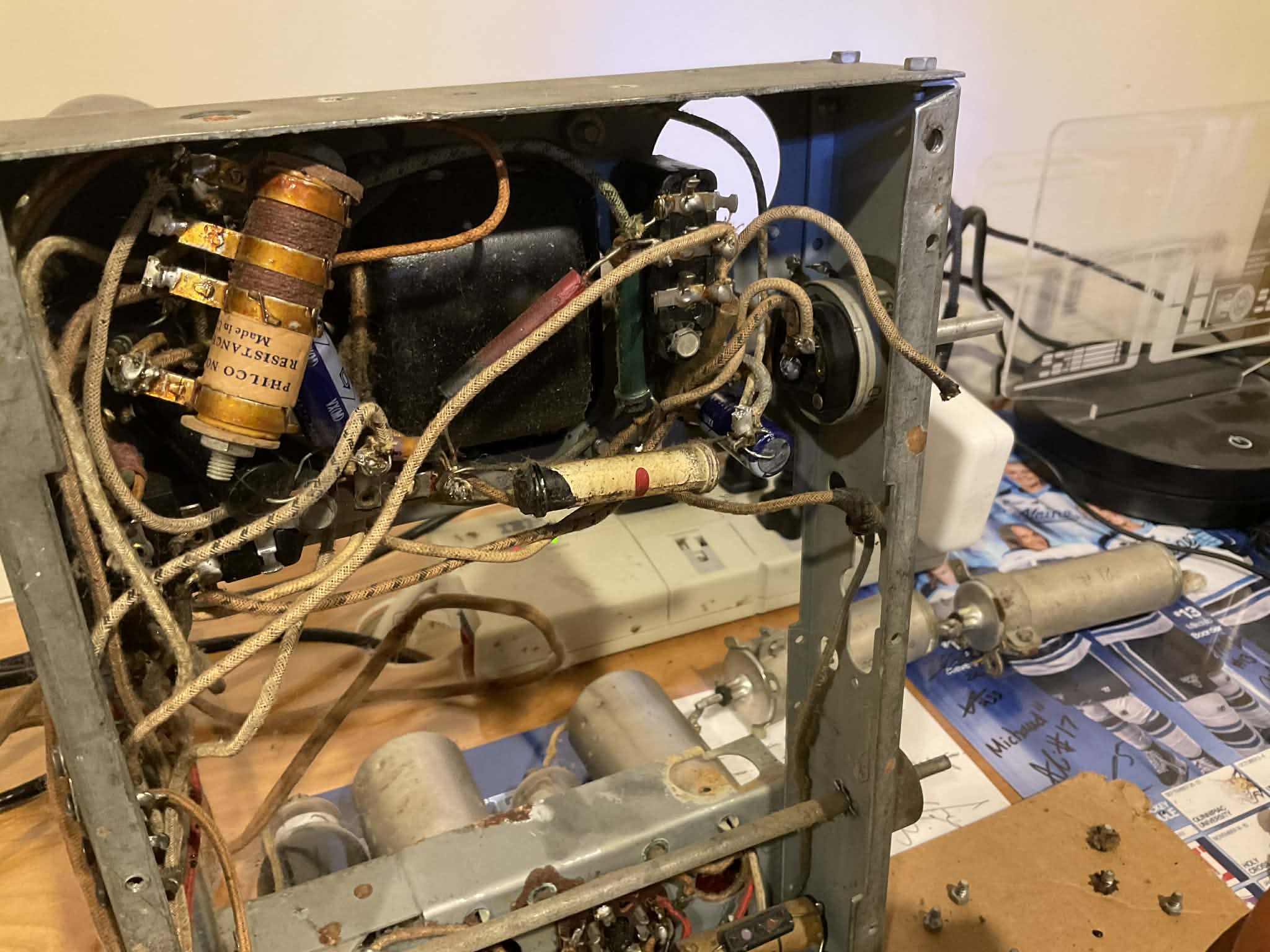
#4 - Just want to verify still if it makes sense that the blue wire (also seen in the photo above) running from the solder terminal strip at position 1 that's supposed to run to the "ON" position of the power switch in the schematics should be spliced and taped to a different wire that bolts down to the bottom right (as pictured) bolt holding the power transformer. It also is just weird to me that it's spliced to a different wire and wrapped in tape. I'm not sure if this was a modification after the fact since it doesn't seem like the way it would come from the factory, but it is definitely old tape. I presume this is one of the hot chassis setups so I guess it could be part of making that circuit.
#6 - Sounds like to be safe I could plan on using 18ga stranded for everything I might feel a need to replace, then. Separately, I noticed one wire that seemed to take a longer route than necessary between ends. As long as I'm not stuffing feet of wire into the chassis, if I find something that needs replacing, is there any difference if I run it one place vs another electrically speaking? With few exceptions, they're all single wires, so not likely a lot of twisting to get rid of EMI.
#7 - I think I'll forgo the idea of a grounded power cord. As a follow-up though, I've read that switching to a polarized plug is a good safety improvement which I'd like to pursue if that's the case. What would the correct way to wire that in? The current cord and schematic don't really give any indication one way or the other. I've also seen it suggested to add a fuse into the circuit for safety. Optimal siting electrically/on the schematic?
Thank you for your earlier answers, Mike. They are very helpful. I have no intent on powering anything on until we're solidly back together with all the possible replacements done. Rod, looking forward to hearing what you see in yours, especially as it may relate to questions 3 and 4 above.
It's amazing how cramped and exposed all these components were, perhaps even more amazing how well it worked AND that there weren't more electrical fires and electrocutions prior to solid state.
Best wishes,
Roy
(PS - unrelated, just picked up an RCA 6K3 this morning for $25 with a reasonably nice cabinet that will need a similar electronic overhaul, but that's a project for another day. Facebook Marketplace, all of about 9 miles away in rural Maine.)
A new question as I prepare to order some components. I went through and tested the resistors (all except one - see notes below) and none test at the ohms the parts list specifies (no surprise I'm sure). Results are below, a couple are somewhat close to spec, others way off. I've read that radios of this era were built to tolerate a variation from spec of up to 20% because of the quality/reliability of the components of the day; also that it's safer to have a little higher than rated than a little under. I'm inclined to replace them all given some of these readings, and given that I hope to never have to take this apart again. Thoughts?
Schematic No - Intended Rating - Measured value
6 - 61,000 ohms - 57,000 ohms (under by 6.6%)
16 - 51,000 ohms - 89,000 ohms (over by 74.5%)
17 - 20,000 ohms - 23,700 ohms (over by 18.5%)
19 - 10,000 ohms - 11,960 ohms (over by 19.6%)
29 - 70,000 ohms - 79,000 ohms (over by 12.9%)
30 - 32,000 ohms - 37,400 ohms (over by 16.9%)
33 - 1,000 ohms - 853 ohms (under by 14.7%)
34 - 400 ohms - 735 ohms (over by 83.8%) - this is the Bakelite, wraps around a paper capacitor that also needs replacing, any special guidance on this one?
39 - 51,000 ohms - 55,100 ohms (over by 8.0%) - might be safe to keep in place?
41 - 490,000 ohms - 500,000 ohms (over by 2.0%) - probably safe to keep in place?
44 - 1,000,000 ohms - 1,500,000 ohms (over by 50.0%)
46 - 51,000 ohms - 49,700 ohms (under by 2.5%)
50 - 1,000,000 ohms - 1,140,000 ohms (over by 14.0%)
53 - 1,000,000 ohms - 1,130,000 ohms (over by 13.0%)
55 - 490,000 ohms - 480,000 ohms (under by 2.0%)
58 - 1,000,000 ohms - 980,000 ohms (under by 2.0%)
64 - 9,000 ohms - could not find in chassis; I see it looks to be between electrolytics #62 and #18 electrically, and connected to a bunch of other things, but it's not on the diagram of the chassis; excerpt of schematic below
Aside from those questions, some follow up to the feedback I've received:
"All paper and electrolytic caps should go, the mica caps stay unless damaged." - Heard and on-board. Electrolytics already replaced, paper will all go for sure, micas can stay. What about the two "Semi-fixed" ones that are inside the tuning circuit? Which category do they fall under? Like the micas, their ratings are in pfd instead of mfd.
#1 - My question about the 8318-SU before was based in the fact that I didn't know the underlying technology inside the bakelite housing(s). Are they effectively equivalent to the paper caps in that sense? I see a lot of talk of "re-stuffing" so I presume they are most often included in re-capping. Follow up, now that I realize it however, I believe the capacitors that replace the electrolytics are polarized; the rest that we're dealing with should not be polarized, correct? So directionality in installation shouldn't matter going forward?
#3 - Expanding on before, I've added a photo below to show the power/tone control. The two power wires go to the lugs at the back (black) part of the pot; at least two lugs appear further in stemming from the metallic section nearer the chassis front. The little wire dangling up and over, floating to nowhere comes off of lug 3 on the 8318-SU which as I mentioned before (on the schematic) looks like it's supposed to connect with part of this pot, but not sure if that's right and if so, which lug to connect to.
#4 - Just want to verify still if it makes sense that the blue wire (also seen in the photo above) running from the solder terminal strip at position 1 that's supposed to run to the "ON" position of the power switch in the schematics should be spliced and taped to a different wire that bolts down to the bottom right (as pictured) bolt holding the power transformer. It also is just weird to me that it's spliced to a different wire and wrapped in tape. I'm not sure if this was a modification after the fact since it doesn't seem like the way it would come from the factory, but it is definitely old tape. I presume this is one of the hot chassis setups so I guess it could be part of making that circuit.
#6 - Sounds like to be safe I could plan on using 18ga stranded for everything I might feel a need to replace, then. Separately, I noticed one wire that seemed to take a longer route than necessary between ends. As long as I'm not stuffing feet of wire into the chassis, if I find something that needs replacing, is there any difference if I run it one place vs another electrically speaking? With few exceptions, they're all single wires, so not likely a lot of twisting to get rid of EMI.
#7 - I think I'll forgo the idea of a grounded power cord. As a follow-up though, I've read that switching to a polarized plug is a good safety improvement which I'd like to pursue if that's the case. What would the correct way to wire that in? The current cord and schematic don't really give any indication one way or the other. I've also seen it suggested to add a fuse into the circuit for safety. Optimal siting electrically/on the schematic?
Thank you for your earlier answers, Mike. They are very helpful. I have no intent on powering anything on until we're solidly back together with all the possible replacements done. Rod, looking forward to hearing what you see in yours, especially as it may relate to questions 3 and 4 above.
It's amazing how cramped and exposed all these components were, perhaps even more amazing how well it worked AND that there weren't more electrical fires and electrocutions prior to solid state.
Best wishes,
Roy
(PS - unrelated, just picked up an RCA 6K3 this morning for $25 with a reasonably nice cabinet that will need a similar electronic overhaul, but that's a project for another day. Facebook Marketplace, all of about 9 miles away in rural Maine.)


