



03-29-2026, 02:20 PM
Mike,
I've added a sketch here of the current configuration where power enters the chassis. Sorry if this seems like basic stuff, but I want to make sure I've got 100% understanding of the particular issues before I start swapping stuff around.
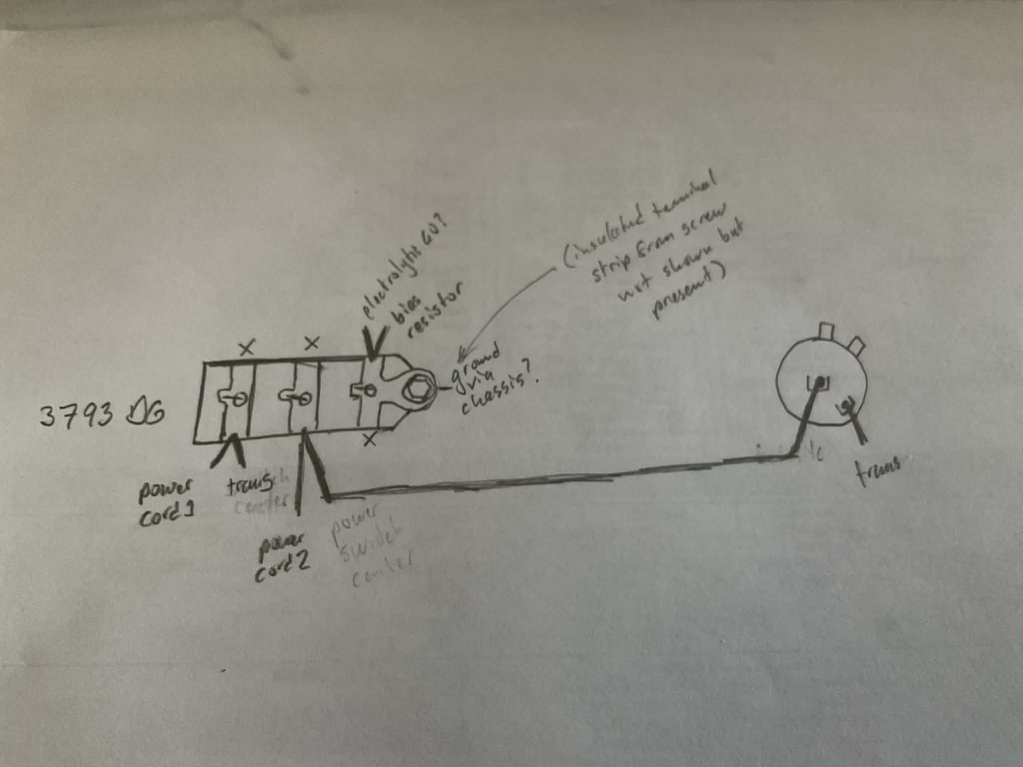
Current power cord (non-polarized) enters chassis, one lead connecting to left-most lug, second lead connecting to center lug.
The left-most lug also has a white wire which goes to the transformer - I suspect this is what on the schematics is marked as WHITE 1.
The center lug has a wire that runs to the center lug on the power/tone control pot
The right-most lug connects to one of the replaced (not by me) electrolytics (I believe number 60) and the bias resistor, and, I suspect, ground via the screw to the chassis.
There is a terminal strip (not illustrated) which branches off of the screw which appears to be insulated and electrically separate for other components to solder to.
On the power/tone control pot, the only other obviously connected lug is the one on the back, adjacent to the center, which is a white wire, also to the transformer (presumably WHITE 2 on the schematic). The other two visible lugs are empty. There may be another lug next to the two empty ones but it's hard to see if it really is a part of the pot, but if it is, it is in contact with the chassis above it - maybe ground for the tone control side?
To move the cap to the right, as you said, are you suggesting to wire it so that the switch is directly connected to one of the leads coming from the power cord, and the output to the place where that lead had originally connected to the capacitor? Does it matter which one? Then, where the capacitor used to run to the switch would go to the transformer directly, yes?
Since I plan to put on a polarized plug end, the prong that is hot (narrow) should be going to the switched side ideally, yes?
As for fuse(s), it's preferable to put them as close to the power cord as possible, before the switch, yes? What rating is best to use for this application?
And lastly, does it seem like the tone control aspect is disconnected if there are only two wires presently connected to the power/tone control pot? Without knowing the purposes to the various lugs on the pot I'm at a loss as to what might be missing. I've looked, but I can't even find pictures of the 42-1182, let alone any reference material. They seem to be scarce and I believe this one is original.
I've added a sketch here of the current configuration where power enters the chassis. Sorry if this seems like basic stuff, but I want to make sure I've got 100% understanding of the particular issues before I start swapping stuff around.
Current power cord (non-polarized) enters chassis, one lead connecting to left-most lug, second lead connecting to center lug.
The left-most lug also has a white wire which goes to the transformer - I suspect this is what on the schematics is marked as WHITE 1.
The center lug has a wire that runs to the center lug on the power/tone control pot
The right-most lug connects to one of the replaced (not by me) electrolytics (I believe number 60) and the bias resistor, and, I suspect, ground via the screw to the chassis.
There is a terminal strip (not illustrated) which branches off of the screw which appears to be insulated and electrically separate for other components to solder to.
On the power/tone control pot, the only other obviously connected lug is the one on the back, adjacent to the center, which is a white wire, also to the transformer (presumably WHITE 2 on the schematic). The other two visible lugs are empty. There may be another lug next to the two empty ones but it's hard to see if it really is a part of the pot, but if it is, it is in contact with the chassis above it - maybe ground for the tone control side?
To move the cap to the right, as you said, are you suggesting to wire it so that the switch is directly connected to one of the leads coming from the power cord, and the output to the place where that lead had originally connected to the capacitor? Does it matter which one? Then, where the capacitor used to run to the switch would go to the transformer directly, yes?
Since I plan to put on a polarized plug end, the prong that is hot (narrow) should be going to the switched side ideally, yes?
As for fuse(s), it's preferable to put them as close to the power cord as possible, before the switch, yes? What rating is best to use for this application?
And lastly, does it seem like the tone control aspect is disconnected if there are only two wires presently connected to the power/tone control pot? Without knowing the purposes to the various lugs on the pot I'm at a loss as to what might be missing. I've looked, but I can't even find pictures of the 42-1182, let alone any reference material. They seem to be scarce and I believe this one is original.


