



03-30-2026, 10:41 PM
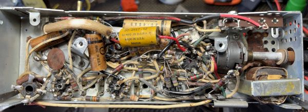
The caps have been replaced and remounted. I did not swap out the wafer cap C10 although that might have to happen in the future. I replaced the selenium rectifier with a 1N4007 diode and added 100 ohm 5 Watt resistor in series with R16 to give a total of 220 ohms after the diode. There was also one bumble bee style cap on the top side of the radio that I swapped out. Since it is visible I did put it inside a paper cap tube that I had although I did have to cut the length of the tube down a bit to get it to fit the space.
When I powered up the set I got good voltage readings at the point just after the added 100 ohm resistor (105vDC) and reasonably close readings at other points around the set. Unfortunately I was hearing absolutely nothing, not even static. After a bit of checking I realized I had put the audio output tube 3V4 in the wrong socket by mixing up with the 1U5(1S5) socket. After swapping them I was getting loud and clear stations.
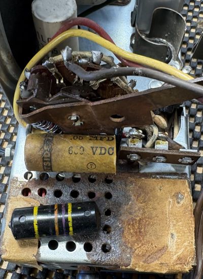
There is still some rust cleanup to do and I have to think about getting the battery connections cleaned up and useable as well. Its clear that the A battery leaked at some point. It uses two P77 batteries for the A voltage and a P144 for the B voltage. There is still some more cabinet work to do.
Here's the voltage check with the 100 ohm resistor still outside the chassis. I was planning on having to try a few different resistors but this one was fine the first time around.
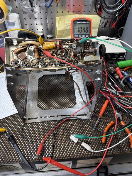
When I powered up the set I got good voltage readings at the point just after the added 100 ohm resistor (105vDC) and reasonably close readings at other points around the set. Unfortunately I was hearing absolutely nothing, not even static. After a bit of checking I realized I had put the audio output tube 3V4 in the wrong socket by mixing up with the 1U5(1S5) socket. After swapping them I was getting loud and clear stations.
There is still some rust cleanup to do and I have to think about getting the battery connections cleaned up and useable as well. Its clear that the A battery leaked at some point. It uses two P77 batteries for the A voltage and a P144 for the B voltage. There is still some more cabinet work to do.
Here's the voltage check with the 100 ohm resistor still outside the chassis. I was planning on having to try a few different resistors but this one was fine the first time around.


