



04-17-2026, 08:47 PM
I contacted Audio Classics. They did service the unit in 2008 and then it came back for additional work in 2009.
I suspect there was someone else, as the Audio Classics go by the official diagram, wheres this mod is not in agreement with the schematic, but was done professionally.
Also heard many interesting things about things going on in McIntosh one year after its latest acquisition by Bose in 2024.
They sent me the latest schematic.
So, I have measured the voltages on the capacitors' outputs.
They are named after their respective voltages, measured at 117V AC input. After having made sure the power switch does not drop anything (it didn't) the measuremets were low.
So, I will put the "expected" and then "measured" values.
268V - 261V
290V - 282V
310V - 295V
The filament voltage (not given but should be 18V as it uses 1-1/2 tubes in series, each 6V) is 16.7V.
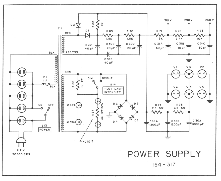
Above the snippet, the power supply of the C22. It is pretty ingenious.
First of, look at the Hi-V part. This is a voltage doubler. But you do not see it linked to GND. This is because they are stacking the voltage of the doubler on top of the filament power supply's voltage which is the Plus of C32A. So, you get some additional 20-25V out of it.
I intend first to replace the first Hi-V rectifier's caps, the C29, C30B/CD. Those are clearly old, the first two are 100uF 200V marked "Apollo" which, I suspect, have not been made at least from 1980s. If this brings the voltages to normal, I will stop; otherwise I will proceed to replace the multi-section cap C31A-C.
I also need to check the resistors. They are not necessarily the values that are declared, but I would like them to be the values that resistors themselves display. In-circuit they are not measured well somehow. I guess the residual voltages, however small, do affect the DMM alot. I will go with the values that are there now, as the resistors had to be recalculated, and I do not want to mess with it: those who serviced it, clearly were pros.
I suspect there was someone else, as the Audio Classics go by the official diagram, wheres this mod is not in agreement with the schematic, but was done professionally.
Also heard many interesting things about things going on in McIntosh one year after its latest acquisition by Bose in 2024.
They sent me the latest schematic.
So, I have measured the voltages on the capacitors' outputs.
They are named after their respective voltages, measured at 117V AC input. After having made sure the power switch does not drop anything (it didn't) the measuremets were low.
So, I will put the "expected" and then "measured" values.
268V - 261V
290V - 282V
310V - 295V
The filament voltage (not given but should be 18V as it uses 1-1/2 tubes in series, each 6V) is 16.7V.
Above the snippet, the power supply of the C22. It is pretty ingenious.
First of, look at the Hi-V part. This is a voltage doubler. But you do not see it linked to GND. This is because they are stacking the voltage of the doubler on top of the filament power supply's voltage which is the Plus of C32A. So, you get some additional 20-25V out of it.
I intend first to replace the first Hi-V rectifier's caps, the C29, C30B/CD. Those are clearly old, the first two are 100uF 200V marked "Apollo" which, I suspect, have not been made at least from 1980s. If this brings the voltages to normal, I will stop; otherwise I will proceed to replace the multi-section cap C31A-C.
I also need to check the resistors. They are not necessarily the values that are declared, but I would like them to be the values that resistors themselves display. In-circuit they are not measured well somehow. I guess the residual voltages, however small, do affect the DMM alot. I will go with the values that are there now, as the resistors had to be recalculated, and I do not want to mess with it: those who serviced it, clearly were pros.
People who do not drink, do not smoke, do not eat red meat will one day feel really stupid lying there and dying from nothing.






