04-21-2026, 09:06 PM
Mike,
Results:
First the Isotap seems to run a little high, so when it appears to be set for 120 V (100 V + 20 V on the two dials), it was actually outputting about 128 V, so that's just something I will keep in mind for the future. I backed it down one step for the test and got about 122 V. I accept that this is old equipment and may have quirks I need to work around. If I get much deeper down the rabbit hole, I will consider new equipment and separate functions (isolation vs variable transformer) as we've previously discussed.
V2: Measuring on both sides of the bulb while in circuit yields approximately 50 V.
V3: With the bulb still in circuit, measuring at the Bakelite where one wire from the cord attaches, and at the center lug of the power switch yields about 77 V. The only thing else in the circuit here is the 1A fuse before the power switch lug.
With the bulb out of the circuit, the same two points in the radio (V3) measure approximately 1 volt lower than the output of the Isotap.
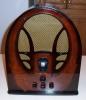
As before, I wasn't really diagnosing the radio at the point of the video, but just testing different configurations for my own curiosity. Also, I wanted to record the bulb in operation for aesthetic purposes - I thought it looked nice in there.
Presently waiting on a lead for the IG-102 signal tester and an appropriate capacitor to begin the alignment.
Best wishes,
Roy