



06-08-2026, 10:01 PM
New 6A8 (and 6K7, just for good measure) arrived today.
I tested tonight first: with original tubes, and second: with just the 6A8 replaced with the new old stock from Bob Dobush. I'll hold the 6K7 in reserve for now.
Also, in the interim between most recent post and today, I received my Deoxit and used it on the power and band switches (D5), and on the volume control (F5). Magically, the power switch started working again, the volume is much smoother, as is the band switch.
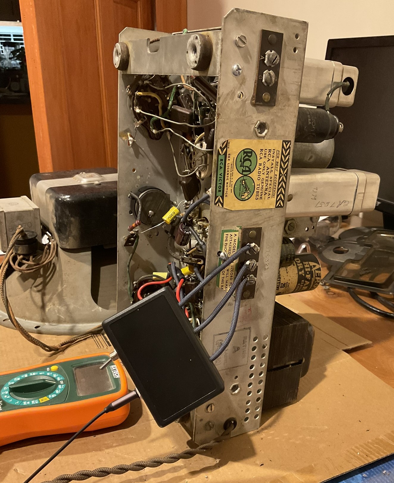
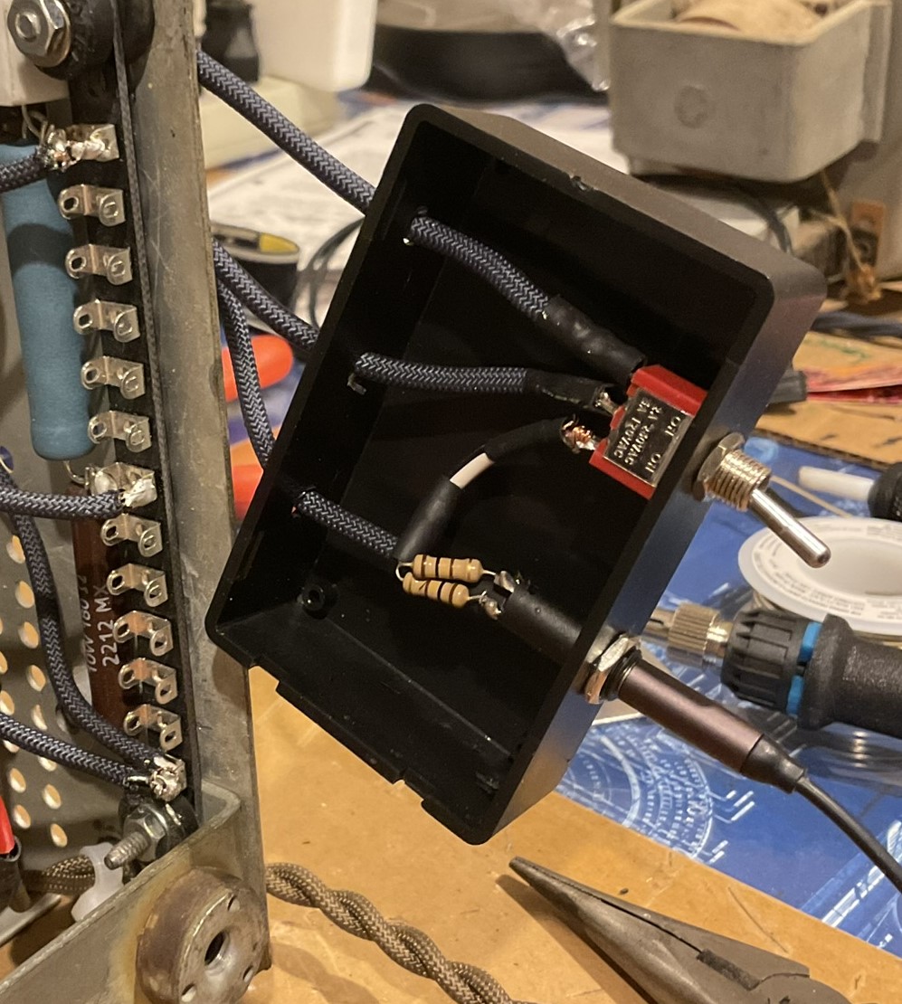
Also, I put in place a switching solution to go between radio and aux input, but this is simply wired to the radio in a removable way, photos below.
With all of these updates in place, my pre-tube swap test was very similar to the last tests:
188V coming off of R14/R15 to R4; 93V on the screen grid pins
After swapping to the replacement 6A8:
189V coming off of R14/R15 to R4; 99.2V on the screen grid pins
To me, this suggests that there might have been some poor switching somewhere that when worked out got us (last time) up from 63V to the 90V area; and second that there may have been some performance issue with the 6A8 that came with the radio that the new tube resolves, getting us up to 99V.
Given that the target for these pins is 100V, I feel like this gets us basically where we're supposed to be in the metric for the screen grids of the 6A8 and 6K7. The radio did seem able to pick up more stations (if not well) than it did before. There are still just a couple local stations, with Boston at about 200 miles away and my antenna solution certainly isn't ideal. Also, my local 1370 AM came in at about 1295, so I'd say it definitely will benefit from an alignment. Timing worked out for me to try Radio Romania International again, and that came in louder and more discernible than before.
My only question now in this phase of troubleshooting is, with 189V coming off of R14/R15 junction, does this bode ill for anything else since it's putting 196V on pin 6 (DP/anode grid)? According to the data sheet for the 6A8, max voltage for that grid is 200 so we're close, but within. Radio documentation specifies 170V. It's obviously also a higher voltage going to the oscillator coil. I double-checked R14 (in-circuit) and it's showing 3.4K (specified 3.5K) so 3% variance - should be well-within tolerance, so I don't think that's the problem.
Aside from this, my next step is to remove the tuning assembly, replace the degraded rubber washers, and clean up the vernier assembly (I'll watch out for any Jesus clips). The tuning knob has been a little stiff since the beginning and the fine-tuning knob just spins (with resistance) without actually adjusting the tuner. I noticed while trying to tune, especially on shortwave, that pressure (not just contact) on the tuning knob/shaft impacts reception, which I suspect may be related to some of the above, even with the new tube.
Photos of the input switch solution which will mount to the cabinet, directly behind the chassis. In this way, there's no modification to the chassis (for this) and is completely removable. It cuts out the output from the RF section beautifully (no bleed through that I can tell yet) and the audio from the aux input is very good quality. I know it's not a period-appropriate switch, but that's not an ultimate concern for me at this point and if it becomes so, I can simply remove it. The cover (removed in the photo showing the interior) will be screwed down to the cabinet and this will snap onto the cover.
Best wishes,
Roy
I tested tonight first: with original tubes, and second: with just the 6A8 replaced with the new old stock from Bob Dobush. I'll hold the 6K7 in reserve for now.
Also, in the interim between most recent post and today, I received my Deoxit and used it on the power and band switches (D5), and on the volume control (F5). Magically, the power switch started working again, the volume is much smoother, as is the band switch.
Also, I put in place a switching solution to go between radio and aux input, but this is simply wired to the radio in a removable way, photos below.
With all of these updates in place, my pre-tube swap test was very similar to the last tests:
188V coming off of R14/R15 to R4; 93V on the screen grid pins
After swapping to the replacement 6A8:
189V coming off of R14/R15 to R4; 99.2V on the screen grid pins
To me, this suggests that there might have been some poor switching somewhere that when worked out got us (last time) up from 63V to the 90V area; and second that there may have been some performance issue with the 6A8 that came with the radio that the new tube resolves, getting us up to 99V.
Given that the target for these pins is 100V, I feel like this gets us basically where we're supposed to be in the metric for the screen grids of the 6A8 and 6K7. The radio did seem able to pick up more stations (if not well) than it did before. There are still just a couple local stations, with Boston at about 200 miles away and my antenna solution certainly isn't ideal. Also, my local 1370 AM came in at about 1295, so I'd say it definitely will benefit from an alignment. Timing worked out for me to try Radio Romania International again, and that came in louder and more discernible than before.
My only question now in this phase of troubleshooting is, with 189V coming off of R14/R15 junction, does this bode ill for anything else since it's putting 196V on pin 6 (DP/anode grid)? According to the data sheet for the 6A8, max voltage for that grid is 200 so we're close, but within. Radio documentation specifies 170V. It's obviously also a higher voltage going to the oscillator coil. I double-checked R14 (in-circuit) and it's showing 3.4K (specified 3.5K) so 3% variance - should be well-within tolerance, so I don't think that's the problem.
Aside from this, my next step is to remove the tuning assembly, replace the degraded rubber washers, and clean up the vernier assembly (I'll watch out for any Jesus clips). The tuning knob has been a little stiff since the beginning and the fine-tuning knob just spins (with resistance) without actually adjusting the tuner. I noticed while trying to tune, especially on shortwave, that pressure (not just contact) on the tuning knob/shaft impacts reception, which I suspect may be related to some of the above, even with the new tube.
Photos of the input switch solution which will mount to the cabinet, directly behind the chassis. In this way, there's no modification to the chassis (for this) and is completely removable. It cuts out the output from the RF section beautifully (no bleed through that I can tell yet) and the audio from the aux input is very good quality. I know it's not a period-appropriate switch, but that's not an ultimate concern for me at this point and if it becomes so, I can simply remove it. The cover (removed in the photo showing the interior) will be screwed down to the cabinet and this will snap onto the cover.
Best wishes,
Roy


