



10-14-2026, 09:59 PM
As another new person to the hobby, welcome. Your 37-630 is very similar to the 37-620 that I just wrapped up.
Looking at the schematics, the bias resistor (R61) should have four lugs, and the negative terminals of the electrolytics should connect through the end lugs. One end lug of the bias resistor should connect to the yellow-green trace wire from the center tap of the transformer; the other end should have a connection to chassis ground. Double-check that you can identify those two characteristics.
The lug with the connection to chassis ground should be the one that connects to the negative terminal of C60 (8 uf) - see photo below. While it may have been different with an original, or original can-style electrolytic, in my photo, the ground connection is to a lug that is grounded to the chassis through the screw mounting the bakelite block to the chassis. Several other components go to ground here. For the C62 (12 uf), the lug that meets the yellow-green trace wire from the power transformer should connect to its negative terminal. Also, the width of the segments of the resistor should correspond to the resistance values specified on the schematic, in this case, the 35 ohm section on the end adjacent to ground, the 8 ohm segment (narrowest) in the middle, and the 202 ohm segment (widest) should connect to the yellow-green trace wire.
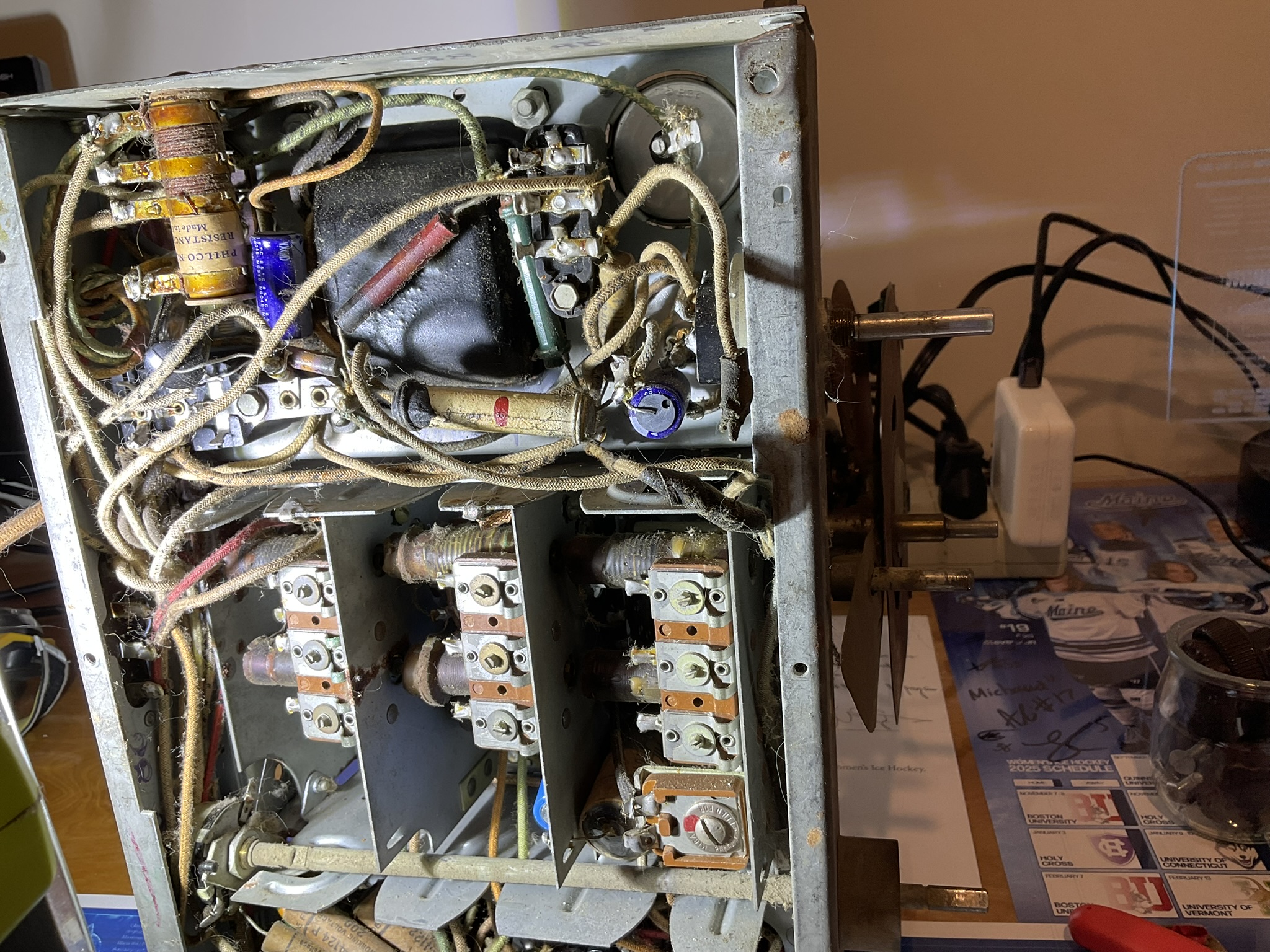
Be cautious, especially with wires whose insulation has faded - there is a white-green trace wire that connects to the positive side of C62 and runs out of the radio to the field coil on the speaker. Since it's nearby, I mention it as something not to confuse with the yellow-green wire from the transformer.
Keep in mind, these connections may not necessarily be directly to the bias resistor itself. C62 is toward the front of the chassis and would be connected via a wire, or at least it was in mine.
For C18 (16 uf), the negative terminal also goes to chassis ground. In my case, it was to a tab on the metal plate separating the oscillator section of the tuning sub-chassis (closest to front) and the center, RF section of the tuning subchassis. See below.
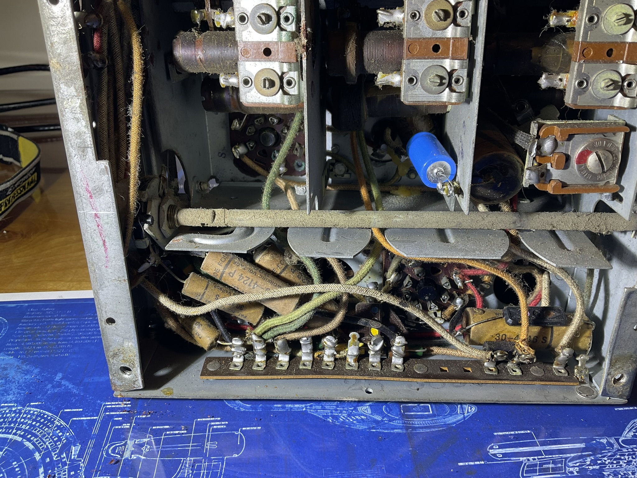
Best thing I find is to find a junction and trace your way from there to other components you can identify and confirm on the schematic.
Hope this helps and as others will undoubtedly express, feel free to ask clarifying questions and share photos. The community here has been of tremendous assistance in just the few months I've been here.
Best wishes,
Roy
Looking at the schematics, the bias resistor (R61) should have four lugs, and the negative terminals of the electrolytics should connect through the end lugs. One end lug of the bias resistor should connect to the yellow-green trace wire from the center tap of the transformer; the other end should have a connection to chassis ground. Double-check that you can identify those two characteristics.
The lug with the connection to chassis ground should be the one that connects to the negative terminal of C60 (8 uf) - see photo below. While it may have been different with an original, or original can-style electrolytic, in my photo, the ground connection is to a lug that is grounded to the chassis through the screw mounting the bakelite block to the chassis. Several other components go to ground here. For the C62 (12 uf), the lug that meets the yellow-green trace wire from the power transformer should connect to its negative terminal. Also, the width of the segments of the resistor should correspond to the resistance values specified on the schematic, in this case, the 35 ohm section on the end adjacent to ground, the 8 ohm segment (narrowest) in the middle, and the 202 ohm segment (widest) should connect to the yellow-green trace wire.
Be cautious, especially with wires whose insulation has faded - there is a white-green trace wire that connects to the positive side of C62 and runs out of the radio to the field coil on the speaker. Since it's nearby, I mention it as something not to confuse with the yellow-green wire from the transformer.
Keep in mind, these connections may not necessarily be directly to the bias resistor itself. C62 is toward the front of the chassis and would be connected via a wire, or at least it was in mine.
For C18 (16 uf), the negative terminal also goes to chassis ground. In my case, it was to a tab on the metal plate separating the oscillator section of the tuning sub-chassis (closest to front) and the center, RF section of the tuning subchassis. See below.
Best thing I find is to find a junction and trace your way from there to other components you can identify and confirm on the schematic.
Hope this helps and as others will undoubtedly express, feel free to ask clarifying questions and share photos. The community here has been of tremendous assistance in just the few months I've been here.
Best wishes,
Roy


