12-08-2013, 02:47 PM
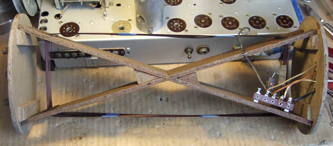
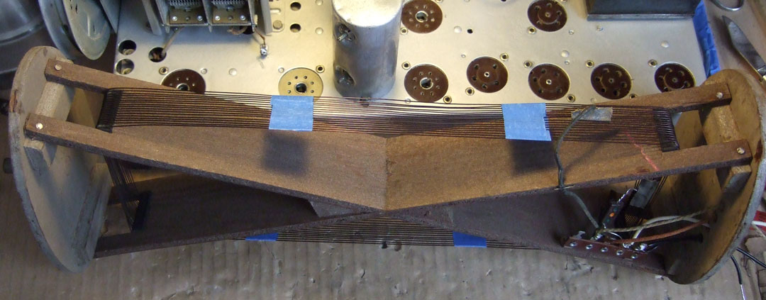
For posterity, I made measurements of the rotatable loop. The dimensions given are just to the corners of the rectangle formed by the internal wooden "X" at the point where the wires bend over the edge: 13.75 inches high by 4.5 inches wide. The distance the wires are evenly spaced across is about 1.25 inches. There is about 1/16 to 3/32 of space between winding loops. Philco used some white tape about 1/3 the distance from the corners along the 13.75 inch height to keep the wires spaced properly so that there are two bands of tape on either side of the loop (total of 4 bands of tape). The total windings are 17. The first loop beginning with the black wire is 3 turns, the second portion is an additional 7.9 loops with the final portion 6.1 turns. The wire connected to the first loop tap is the white - yellow (or in this case just white), the second portion tap is the white - red (or in this case just red) and the remaining tap at the end is the white - green wire. On this radio the black wire and the white wire were the rubber insulated types. The red wire and the white - green wires were cloth covered types. The white wire connects to the junction of the 250pfd cap and the 10k ohm resistor and is brought out to the terminal at the back of the chassis. The white - green wire connects to terminal 1 of the 4-terminal strip. the white - red or red wire connects to terminal 2 of the 4-terminal strip. The white wire from the junction of the 10k ohm resistor and 250pfd cap connects to the 2nd. terminal (right side terminal) of the 2-terminal strip to the right of the 4-terminal strip location. The wire used for the loop is 21AWG magnet wire, measuring about 0.029 inches in OD. Each section of the loop measures in fractions of an ohm.
There is one loop shown close to the dashed lines of the rotatable antenna and this loop is in the top of the cabinet with a cloth covered wire brought down to connect at the 3rd. terminal next to the 4th. terminal where the black wire connects to the terminal strip with 4 terminals. This is the loop shown on the schematic with a resistance of less than 0.1 ohms. I have not looked to see how many turns, how spaced or what wire size was used yet. That item is still in the cabinet and it is in the barn. It is still freezing outside and it will have to wait until the weather is warmer.
Joe


![[-] [-]](https://philcoradio.com/phorum/images/bootbb/collapse.png)


