Thread Rating:
  • 0 Vote(s) - 0 Average
  • 1
  • 2
  • 3
  • 4
  • 5

Unusual Audio Output Circuit
#1

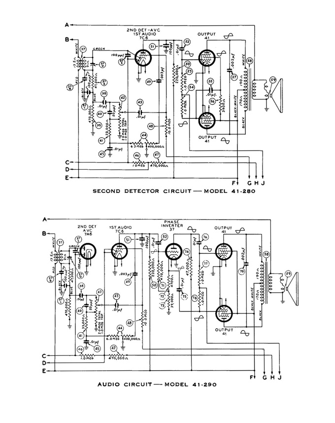
I recently looked at the schematics of a 41-290 to help a friend and in the process noticed the difference between the Williamson type output circuit used in it versus the output schematic of the 41-280. The 41-280 does not use the Williamson design, yet still achieves a push-pull output stage. At first glance I could not figure out how it worked. Thanks to another amateur radio friend the explanation became understandable. You have to look at the phase relationships as waveforms move through the tubes. I took the liberty of adding waveforms to the schematics so people could see the phase relationships. In the 41-280 the screen grid of the top output tube is not bypassed until it gets past resistor 56, a 3900 ohm resistor. This voltage which is in phase with the signal at the plate is coupled to the grid of the bottom tube's grid thereby making its output opposite in phase to the tube above it, thus achieving a push-pull circuit. In effect the output tubes become a phase inversion circuit as well as an output gain stage. A whole tube is eliminated in the process, thus reducing costs.

Joe


Messages In This Thread
Unusual Audio Output Circuit - by Joeztech - 01-12-2014, 09:13 AM
RE: Unusual Audio Output Circuit - by codefox1 - 01-12-2014, 05:48 PM
RE: Unusual Audio Output Circuit - by Joeztech - 01-12-2014, 06:39 PM
RE: Unusual Audio Output Circuit - by BrendaAnnD - 01-12-2014, 10:31 PM
RE: Unusual Audio Output Circuit - by Arran - 01-12-2014, 11:28 PM
RE: Unusual Audio Output Circuit - by hsusmann - 01-13-2014, 03:21 PM
RE: Unusual Audio Output Circuit - by hsusmann - 01-26-2014, 02:50 PM
RE: Unusual Audio Output Circuit - by Randy H. - 01-26-2014, 06:41 PM
RE: Unusual Audio Output Circuit - by Joeztech - 01-27-2014, 06:44 AM
RE: Unusual Audio Output Circuit - by Radioroslyn - 01-27-2014, 07:12 AM
RE: Unusual Audio Output Circuit - by codefox1 - 02-02-2014, 07:42 PM


Users browsing this thread: 1 Guest(s)
[-]
Recent Posts
Cannot Adjust an IF Transformer’s cores
It works! I received the PCBs this morning in the mail, and put everything together. I reused the base from the original...jrblasde — 04:32 PM
PT-6 antenna connections
I seem to have lost my way on this PT-6. I see the antenna aerial transformer schematic - I’m reading pins 1 through ...bridkarl — 12:30 PM
40-150 General questions
Good thing you're a good electrician ... the pictures show a lot of rewiring in your future! Take care and BE HEALTHY!...GarySP — 11:52 AM
40-150 General questions
I think RobB has it right. It is a part number and looks like its stamped on the chassis and that wasn't something you ...klondike98 — 11:41 AM
40-150 General questions
It's most likely a part number. Most of Philco part numbers are in that format. I looked at the parts list for this mode...RodB — 08:10 AM
40-150 General questions
Hi Kevin, No, I don't but I like your Quote about being a good electrician. The way I look at it is "The fact ...MrFixr55 — 08:06 AM
Philco 38-7 Speaker
7K should be fine. While not a perfect match (This transformer is meant for 6V6 tubes), Antique Electronic Supply (AES)...MrFixr55 — 08:03 AM
40-150 General questions
I discovered a stamp on the underside of the breadboard on my Philco 40-150. It is"56-1417' in black ink with numbe...Kevin_D — 07:14 AM
Philco 38-7 Speaker
FYI the Impedance of the HR20 (the one I have) secondary of the audio transformer is 5 ohms. The 38-7XX speaker is suppo...tludka — 04:22 PM
Philco 38-7 Speaker
Yeah, don't use the transformer currently on the H-20 (Dopf, I thought "H20, is that new technology, a speaker usin...MrFixr55 — 03:51 PM

[-]
Who's Online
There are currently 2486 online users. [Complete List]
» 1 Member(s) | 2485 Guest(s)
Avatar

>