07-29-2014, 05:43 PM
Sorry for the delay in replying to all of you kind people for your generous help. A little thing called a job has a bad habit of taking away from my radio hobby  As such, I got home and went downstairs to take a few pictures of what I'm dealing with.
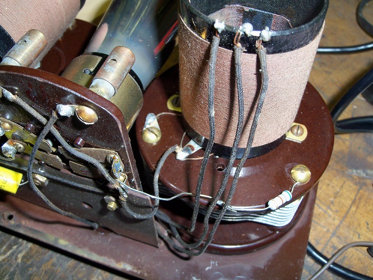
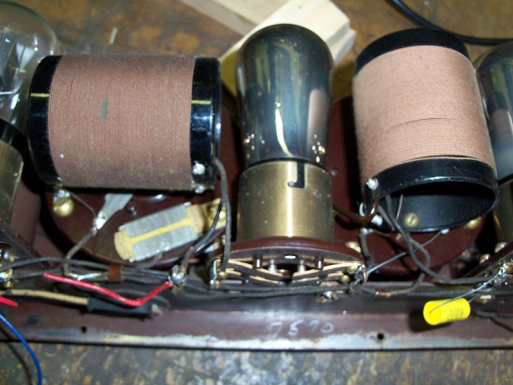
When I received this set, all of the original wirewound resistors in series with the tuning caps were missing and replaced with 'modern' resistors, albeit of the wrong value. There were 1000 ohm resistors instead of the 600 ohm's called for on the schematic (link in my first post). I replaced them with 680 ohm's, as that's the closest I had on hand until I order the correct one's. I figured they are closer than the 1000's that were in the set when I got it, and the minor difference from 600 to 680 shouldn't prevent the set from receiving. They are soldered to the grid terminal of the 1R and 2R UX-201 tubes, and the other end attached to the screws on each of the two tuning capacitors. Can anyone tell me if that is how the original wirewound one's were attached to the T C's? See pics below:
1R:

2R:
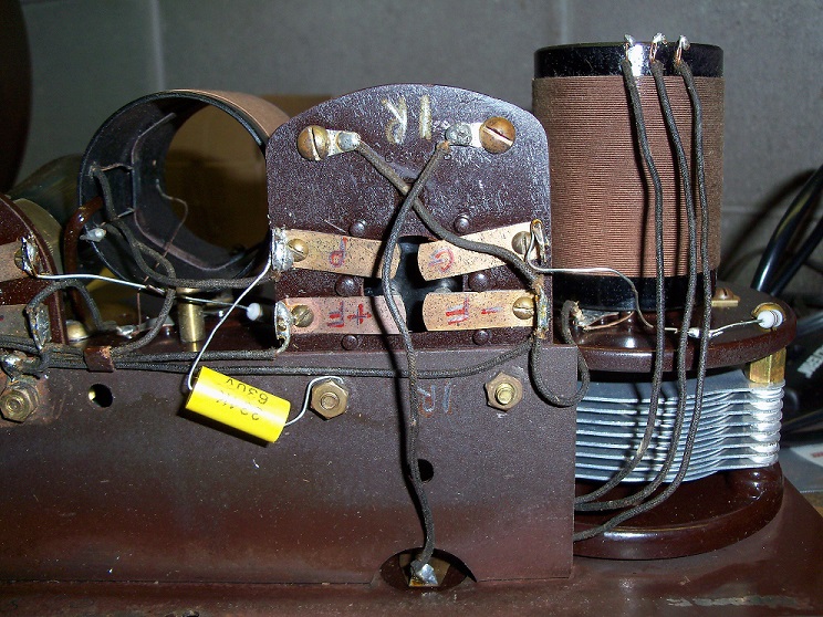
(See the last pic in this post)
Under the 2R you can see the .3 mfd RF Bypass Condenser I replaced with a .33 mfd. It was missing altogether on my set.
The 250 pf Grid Condenser, seen in the pic below, checks out fine. I tried disconnecting it and gator wiring in a modern 250 pf capacitor with no difference.

Here's a bottom view of the 1R section for reference. Sometimes it's better to have more sets of eyes looking at a project that may see something amiss that I might be missing. So I welcome your thoughts / ideas on why, despite the audio output section working fine up to the Grid Condenser, I'm not able to receive any stations, only static that varies with intensity as I increase or decrease the rheostats.

Can anyone explain exactly the function of the 3 position antenna knob?

Is it a low / medium / high sensitivity?
When I received this set, all of the original wirewound resistors in series with the tuning caps were missing and replaced with 'modern' resistors, albeit of the wrong value. There were 1000 ohm resistors instead of the 600 ohm's called for on the schematic (link in my first post). I replaced them with 680 ohm's, as that's the closest I had on hand until I order the correct one's. I figured they are closer than the 1000's that were in the set when I got it, and the minor difference from 600 to 680 shouldn't prevent the set from receiving. They are soldered to the grid terminal of the 1R and 2R UX-201 tubes, and the other end attached to the screws on each of the two tuning capacitors. Can anyone tell me if that is how the original wirewound one's were attached to the T C's? See pics below:
1R:
2R:
(See the last pic in this post)
Under the 2R you can see the .3 mfd RF Bypass Condenser I replaced with a .33 mfd. It was missing altogether on my set.
The 250 pf Grid Condenser, seen in the pic below, checks out fine. I tried disconnecting it and gator wiring in a modern 250 pf capacitor with no difference.
Here's a bottom view of the 1R section for reference. Sometimes it's better to have more sets of eyes looking at a project that may see something amiss that I might be missing. So I welcome your thoughts / ideas on why, despite the audio output section working fine up to the Grid Condenser, I'm not able to receive any stations, only static that varies with intensity as I increase or decrease the rheostats.
Can anyone explain exactly the function of the 3 position antenna knob?
Is it a low / medium / high sensitivity?
Greg V.
West Bend, WI
Member WARCI.org


![[-] [-]](https://philcoradio.com/phorum/images/bootbb/collapse.png)


