RCA V-210 field coil removal
Posts: 116
Threads: 25
Joined: Jul 2006
City: Lebanon, NJ 08833
Thanks, EdHolland. I found an old 5lb spool of non ROHS 34AWG magnet wire here at work and we have an old winding machine that is used for prototyping which I can use. I just have to design a mandrel to mount and hold the bobbin.
I measured and calculated the voice coil gap to be about 0.040" and the diameter is 1", so to center the pole piece when pressing it back in I need to find a circular tube of that thickness and outer diameter. It can be metal, plastic, FR4 or even cardboard as long as it centers the pole piece and doesn't move as I press it it. We have a number of FR4 tubes that we use for bobbins and HV insulators here at work so I will have to search through them and hopefully I'll find a suitable one or one that I can machine to the proper dimensions.
Steve D
Posts: 2,118
Threads: 112
Joined: Jun 2010
City: Medford OR (OR what?)
One of the biggest issues with rewinding is supporting the coil-form cheeks. So wen you build your mandrel, try to add some large washers to keep the wire from making the coil "fat".
"I just might turn into smoke, but I feel fine"
http://www.russoldradios.com/
Posts: 116
Threads: 25
Joined: Jul 2006
City: Lebanon, NJ 08833
You are right, Phlogiston, I removed all the winding wire from my coil and the bobbin is intact but very fragile. The cheeks are thin cardboard and will deform when winding. My next task it to design a mandrill and cheek support.
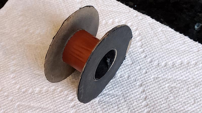
I want the coil to appear original and if the sides are too flimsy I'll make new ones from a different material and cover them with the old cardboard ones. Some experimenting to do.
Steve D
Posts: 5,182
Threads: 276
Joined: Nov 2012
City: Wilsonville
State, Province, Country: OR
Nice work! More than I would take on but you might save this one!

Posts: 116
Threads: 25
Joined: Jul 2006
City: Lebanon, NJ 08833
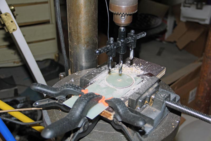
So I finally got some time to work on the field coil this past weekend. I made a new bobbin from some 0.030" FR4 sheet and 1.25"OD, 0.062" wall thickness FR4 tube.
Cutting the bobbin cheeks with a fly cutter:
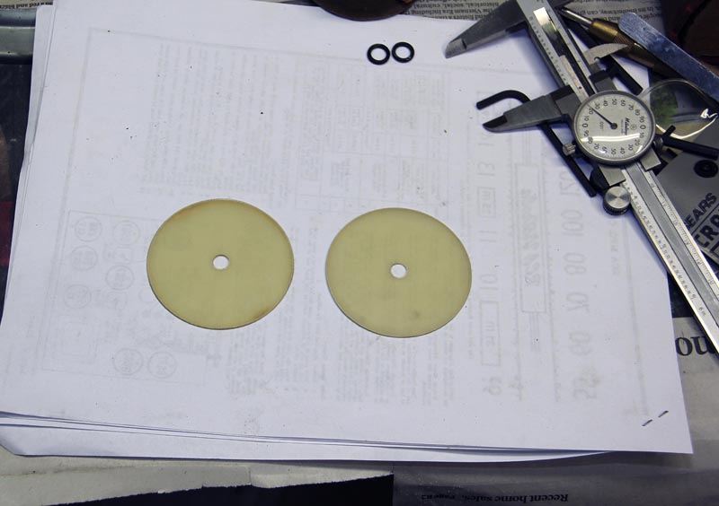
Pieces ready for assembly:
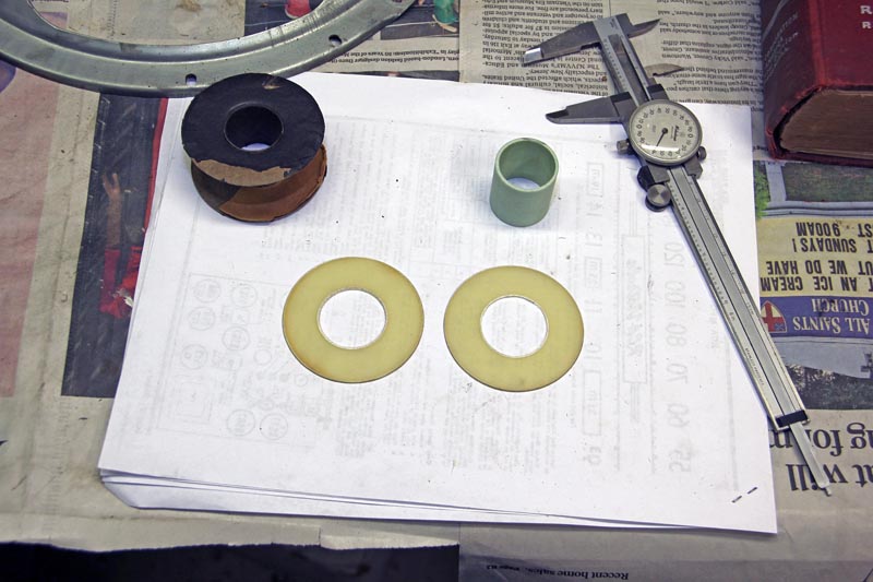
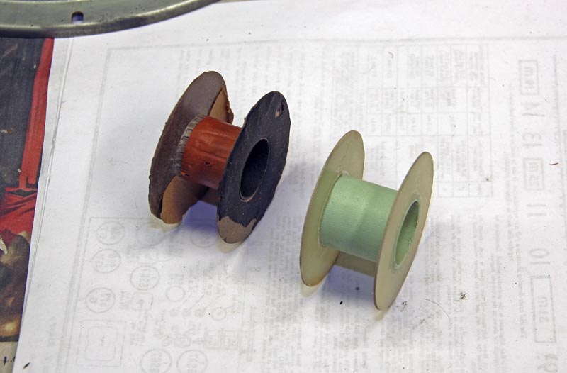
Next I epoxied the cheeks to the tube (original bobbin shown for reference):
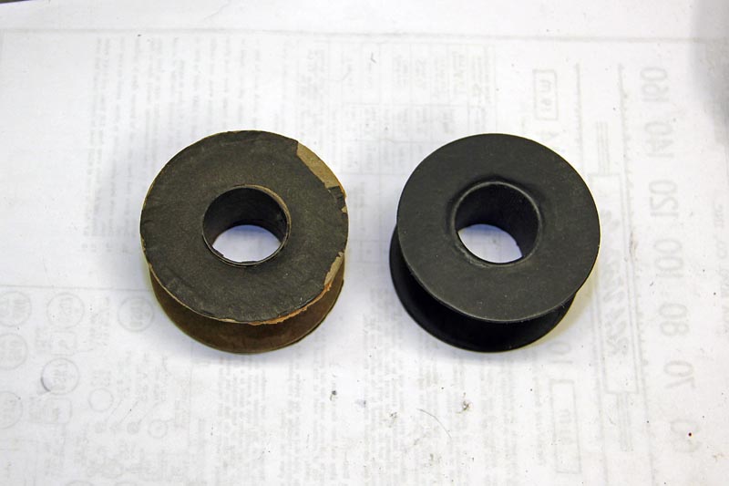
Lastly I painted the bobbin flat black to match the original:
Posts: 116
Threads: 25
Joined: Jul 2006
City: Lebanon, NJ 08833
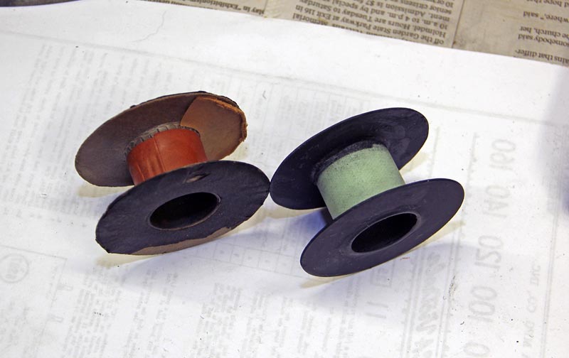
Another shot of the new bobbin:
The next step is to make a setup to allow unspooling of the wire while maintaining tension and a method to guide the wire across the bobbin.
Steve D
Posts: 116
Threads: 25
Joined: Jul 2006
City: Lebanon, NJ 08833
Continued from the previous post:
Finished coil:
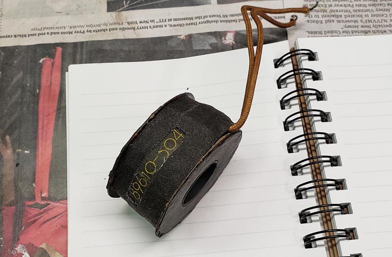 The coil fits the pole piece and speaker frame perfectly, so the next step is to press the pole piece back into the frame while maintaining a uniform .032” voice coil gap.
After I wound this coil, out of curiosity, I re-glued the FR4 bobbin with JB weld and using the side supports wound another coil. It also wound perfectly, so now I have a spare coil or a nice inductor for any filtering needs.
Steve D
Posts: 116
Threads: 25
Joined: Jul 2006
City: Lebanon, NJ 08833
Finishing up the speaker:
I made the centering collar from four strips of 0.010 Teflon material which is what I had on hand and cut each piece successively longer to maintain the same length when wrapped around the pole piece. This resulted in a thickness of nominally 0.040 and the gap appears to actually be closer to 0.038” and when compressed into the slot, fit nice and evenly tight all around.
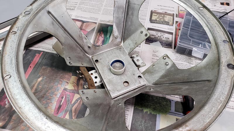 With this arrangement I was able to easily press the pole piece back in and the resultant gap was beautifully uniform:
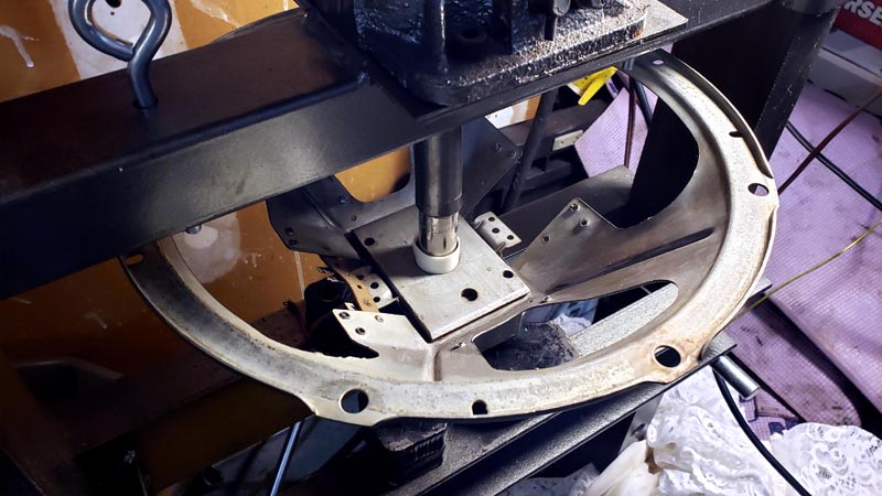
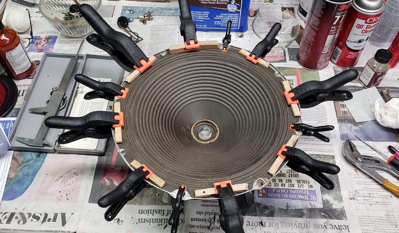
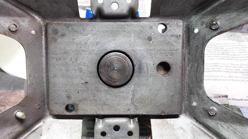 Next I used small strips of .007” paper to center the voice coil while I screwed the spider assembly in and glued the edges of the cone. I had to remove the cone center cap to access the voice coil to insert the centering strips:
Continued in next post.
Steve D
Posts: 116
Threads: 25
Joined: Jul 2006
City: Lebanon, NJ 08833
Lastly, I glued the cone center cap back on and made all the electrical connections:
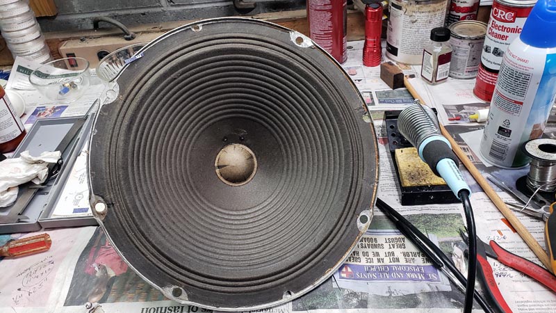
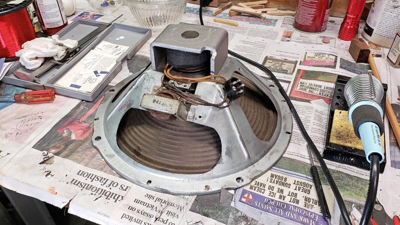 Now I just have to finish refurbishing the chassis to power it up. Hopefully it will play clearly.
This was a lot of work and a good experience and I’m glad I saw it through, but next time perhaps I’ll try harder to find a replacement speaker.
Steve D
Posts: 16,533
Threads: 573
Joined: Oct 2011
City: Jackson
State, Province, Country: NJ
Great job!
Laborious process too.
People who do not drink, do not smoke, do not eat red meat will one day feel really stupid lying there and dying from nothing.
Posts: 112
Threads: 36
Joined: May 2015
City: Brandon, SD
I had a replacement speaker the whole time, just never heard from you again....
Posts: 116
Threads: 25
Joined: Jul 2006
City: Lebanon, NJ 08833
Success, I got the chassis working and the speaker sounds great; loud and clear with no rattling, rubbing or distortion. The field coil drops the correct voltage and I Just need to do an alignment and refurb the turntable and cabinet. This was an enjoyable but laborious process which was worthwhile as I gained experience in speaker design but I probably would only do it again for a speaker that is unobtainum.
Steve D
Users browsing this thread: 1 Guest(s)
|
|
Recent Posts
|
|
1949 Motorola 5A9M
|
| This would be the second portable in the "other radios" forum where I have a similar one in my collection. I h...Arran — 12:41 AM |
|
Looking for any info: 1977 Ford-Philco Console Hi-Fi Turntable and Radio
|
| Hi PittsburgTost.
The record changer looks like a Garrard or BSR (Likely Garrard). The spindles just pull out and pu...MrFixr55 — 11:57 PM |
|
Looking for any info: 1977 Ford-Philco Console Hi-Fi Turntable and Radio
|
| Hello PittsburghToast ,
Welcome aboard and it looks like gary may have something for you !
now if I dig through my se...radiorich — 11:35 PM |
|
Model 80 Antenna Issue?
|
| You are kind of on the right path. You can touch the grid cap of the Detector/Oscillator 36 tube. I'm expecting a respon...RodB — 08:48 PM |
|
Looking for any info: 1977 Ford-Philco Console Hi-Fi Turntable and Radio
|
| Welcome to the Phorum, PittsburghToast! I found an old thread that my interest you regarding the quality and worth of P...GarySP — 08:48 PM |
|
Looking for any info: 1977 Ford-Philco Console Hi-Fi Turntable and Radio
|
| Welcome to the Phorum!
:wave:
We do not have anything on that unit in our digital library. There is a Sam's Photof...klondike98 — 08:47 PM |
|
Model 80 Antenna Issue?
|
|
I’ve replaced all the caps and resistors and the radio is working but minimal volume unless I put my hand near the re...Hamilton — 08:24 PM |
|
Looking for any info: 1977 Ford-Philco Console Hi-Fi Turntable and Radio
|
| Hi there! this is my first time posting. I recently picked up this Ford-Philco Console record player and radio at a yard...PittsburghToast — 07:28 PM |
|
philco predicta
|
| I found that where I have the 140v B+ there is 50v and the tuner receives 235v through the orange cablecgl18 — 04:14 PM |
|
Philco 91 code 221
|
| Chassis grounds thru rivets is another good place to look. Oh and the stator screws on the tuning cap where the leads at...Radioroslyn — 08:11 AM |
|
Who's Online
|
| There are currently no members online. |

|
 
|


![[-] [-]](https://philcoradio.com/phorum/images/bootbb/collapse.png)


