Posts: 7,305
Threads: 270
Joined: Dec 2009
City: Roslyn Pa
Correct. It's the small most outer winding. It's also the one that fails via decay. It is there to create feedback to cause the oscillator to run. A bit like a regenerative receiver w/o the fones
When my pals were reading comic books
I was down in the basement in my dad's
workshop. Perusing his Sam's Photofoacts
Vol 1-50 admiring the old set and trying to
figure out what all those squiggly meant.
Circa 1966
Now I think I've got!
Terry
(This post was last modified: 09-10-2020, 08:11 AM by Radioroslyn.)
Posts: 13
Threads: 1
Joined: Aug 2020
City: Corrales
State, Province, Country: NM
Terry,
Interesting. Very helpful. I’ll get back into the Philco in a day or two. I’ll let everyone know how it goes. Working on an AA6 now...finally recapping it.
R
Posts: 1,168
Threads: 45
Joined: Feb 2015
City: Roseville, MN
Yes, Terry, that's correct. I missed that. It's an oscillator in a tank circuit, no wonder it's touchy. I would also look at the cathode bypass cap. I once fixed an amplifier tremolo circuit that had a bad cathode bypass.
Posts: 7,305
Threads: 270
Joined: Dec 2009
City: Roslyn Pa
It is kind of a primitive circuit. The older sets (70) used two tubes to perform the mixing duties. Seems like there would be some interaction between osc frequency and the peak adjustment of the 1st IF. The 36 tube (tetrode) needs a suppresser grid but such was the technology in 1932. The generation sets used the 39/44 a full fledged pentode.
When my pals were reading comic books
I was down in the basement in my dad's
workshop. Perusing his Sam's Photofoacts
Vol 1-50 admiring the old set and trying to
figure out what all those squiggly meant.
Circa 1966
Now I think I've got!
Terry
(This post was last modified: 09-10-2020, 10:36 AM by Radioroslyn.)
Posts: 1,199
Threads: 49
Joined: Oct 2017
City: Allendale, MI
For grins and giggles, I pulled my 71 off the shelf and looked at the oscillator signal on the scope taking the signal at the cathode. Beautiful sign wave at 1500 kc. Amplitude went down as I tuned lower. Plus the shape of the waveform degraded severely. The cathode resistor is original and measures 11k. I paralleled another resistor to bring the cathode resistor down to about 8.4 k. The cathode waveform on the low end of the dial increased substantially, though still distorted. At the high end of the dial, the waveform was good but with slightly less amplitude than without the resistor. I left it in the circuit cuz the radio seems work a bit better on the low end of the dial.
(This post was last modified: 09-10-2020, 05:11 PM by rfeenstra.)
Posts: 13
Threads: 1
Joined: Aug 2020
City: Corrales
State, Province, Country: NM
Fun. Good to know. My alleged 15K resistor (as marked) measured 12.5K, and ironically, I, too used a parallel resistor and ended up with 8.4K. My LO was then good to about a receive frequency of 600 khz before all reception stopped at lower frequencies, because the LO quit. But right now, the LO has quit totally (again) and the receiver is dead everywhere.
I sometimes wonder how the osc tube would respond to higher B+.
Anyway, I’ll get back to this sad little oscillator this weekend.
R
Posts: 1,199
Threads: 49
Joined: Oct 2017
City: Allendale, MI
I did have to rewind the oscillator coil on my 71.
Posts: 13
Threads: 1
Joined: Aug 2020
City: Corrales
State, Province, Country: NM
Was it fully open, or intermittent? My osc comes and goes at will. Since I’ve not pulled mine out, how many turns does it have? And what insulating material did you wind it on (separating the windings)?
Posts: 1,199
Threads: 49
Joined: Oct 2017
City: Allendale, MI
I don't remember. I probably looked at it and saw the typical green corrosion. If it wasn't bad yet, it would have been in the future. So I rewound it. Any Philco with the nitrocellulose insulation is suspect.
Posts: 1,199
Threads: 49
Joined: Oct 2017
City: Allendale, MI
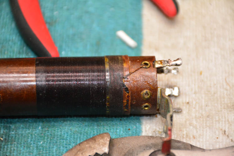
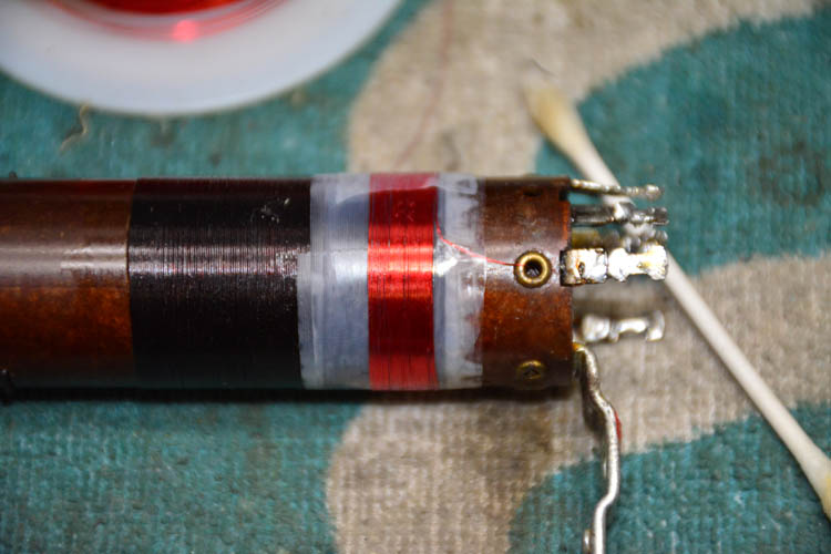
Here is a before and after pic. The coil does not look bad as i don't see any green. But I probably figured it would go bad eventually.


After the original winding was removed, the coil was baked and then sealed with lacquer.
Posts: 13
Threads: 1
Joined: Aug 2020
City: Corrales
State, Province, Country: NM
An update. The intermittent local oscillator refuses to quit, as usual, now that it’s on the workbench. I got it running by the usual ”shock excitation” method by touching the grid of the 36 osc/mixer with a short test lead. And now, it won’t quit. Plays for hours. When it finally does die, again, I’ll check voltages. But running properly, it has 90 Volts on the screen and about 260 on the plate...that should be more than enough to keep it oscillating.
Richard
(This post was last modified: 09-14-2020, 07:10 PM by WB5NEN.)
Posts: 7,305
Threads: 270
Joined: Dec 2009
City: Roslyn Pa
Is the feedback winding rewound? Same direction as original and wire ga around 38ga?
When my pals were reading comic books
I was down in the basement in my dad's
workshop. Perusing his Sam's Photofoacts
Vol 1-50 admiring the old set and trying to
figure out what all those squiggly meant.
Circa 1966
Now I think I've got!
Terry
Posts: 13
Threads: 1
Joined: Aug 2020
City: Corrales
State, Province, Country: NM
Terry,
I have not rewound the feedback coil, because it shows good continuity. I have, however, thought about rewinding it just to get a few extra turns in a (probably foolish) attempt to provide more feedback. Once it quits again, and if I find voltages are still what they should be on the tube, I will also check the coil for continuity.
But if this sounds like I’m taking the wrong path, let me know!
Richard
Posts: 13
Threads: 1
Joined: Aug 2020
City: Corrales
State, Province, Country: NM
Update. I need my workbench cleared from the Model 71 woes. The 71 is still playing, the LO is (for the moment) still oscillating, and I am poor at troubleshooting a working circuit. I put the 71 back in the cabinet, put it in its permanent place, it’s still working, so I will move on to another project (replacing a busted belt on a console Zenith). Thanks to everyone. Sorry for the lack of resolution.
Richard
Users browsing this thread: 1 Guest(s)
|
|
Recent Posts
|
|
Rogers Majestic R-646
|
| Today I finished inspecting all the parts. The result is not very pleasing.
The first positive news:
1) The power tr...Vlad95 — 11:40 PM |
|
HiFi (Chifi) tube amp build - but my own design.
|
| Well, found muh culprit. After using socket test adapters and finding voltages all ok, swapping 6V6s, no avail, swapped ...TV MAN — 11:18 PM |
|
HiFi (Chifi) tube amp build - but my own design.
|
| Well, maybe - maybe not :lol: It's been an interesting project so far! Something so simple, yet so cranky. The 1st one ...TV MAN — 05:12 PM |
|
1949 Motorola 5A9M
|
| Haven't thought of Burgess batteres in a while
https://www.radionostalgia.ca/lib/Images/battery/us/burgess1D.jpgi
...Vlad95 — 03:50 PM |
|
Philco Model 16 wiring question
|
| Measure the voltages first, just in case.morzh — 02:19 PM |
|
1949 Motorola 5A9M
|
| Haven't thought of Burgess batteries in a while Mr. Fixer. Boston Edison always used Burgess in their Bright Star yellow...Paul Philco322 — 02:17 PM |
|
1949 Motorola 5A9M
|
| Thanks Sam. I'll let you know. I can probably scare some up from the local radio club.klondike98 — 02:07 PM |
|
Philco 89 Code 123 Osc Coil
|
| Hello,
I thought I would post my findings on my bad oscillator tickler coil. There were 27 turns on the outer coil b...dconant — 12:38 PM |
|
Philco Model 16 wiring question
|
| Thanks Morzh. So it appears I did wire it incorrectly and I have to switch the wires between pins 2 and 4.bobclausen — 09:24 AM |
|
Philco 46-1209 strange behavior
|
| No, it's not a problem, just during certain condition it could show up.
Yes, an internal tube short could do that too.
...morzh — 09:13 AM |
|
Who's Online
|
| There are currently no members online. |

|
 
|


![[-] [-]](https://philcoradio.com/phorum/images/bootbb/collapse.png)


