Posts: 1,205
Threads: 11
Joined: Jul 2020
City: Greenlawn
State, Province, Country: NY
Hi Chas,
By SW-3 are you describing the National SW3? Are you describing L1? Yes, I expect that one to have a high inductance, as it is iron core and blocks high frequencies from the B+ supply, and, yeah, it being a regenerative detector, it is a good idea to have a 700H (??) choke there. The ones in series with the detector plate and the coupling cap (L2 and L3) are 2.5mH and 5.5mH air core units.
My recommendation to sub resistors for the chokes were merely to move forward with testing the radio. If it works but unsatisfactory performance can be traced to the absence of L11 and L12, then the effort in duplicating them can be spent.
Best Regards,
John
"Do Justly, love Mercy and walk humbly with your God"- Micah 6:8
"Let us begin to do good"- St. Francis
Best Regards,
MrFixr55
Posts: 16,476
Threads: 573
Joined: Oct 2011
City: Jackson
State, Province, Country: NJ
I do not expect problems because of L12, as R-73-A changed the circuitry to use RC filter instead. This is just it, a power supply filter.
L11 will affect performance, but yes, to move forward putting 3K resistor would help, provided the rest of it is OK (I still have not checked the driver transformer).
People who do not drink, do not smoke, do not eat red meat will one day feel really stupid lying there and dying from nothing.
Posts: 16,476
Threads: 573
Joined: Oct 2011
City: Jackson
State, Province, Country: NJ
OK. After having thought about it, and then looking at some other RCA contemporaries (like R-7 Superette) I think I know what this choke is for and what value it should have.
If one looks at the Superette sch, it shows a choke used in the same way, but with much lower DC value. Like 80 Ohms.
Then something told me, that this tibe, 55, being both 2nd detector and Pushpull driver, might be simply using an RF choke, in the same way Philco 70 or 90 use it after the plate detector, to simply filter RF from getting to the output of the tube. So the value of the similar chokes being a few mH, this is probbaly what it should be. from 1 to 5 mH. A filter together with C23.
It is certainly NOT there to compensate for frequency response on low. If anything, at low frequencies the reactance of the primary's inductance is across the load, and, being low, it diminidhes the Low output. Adding another inductance will simply divide the signal further between that shunted load and that choke.
And at high it will be in series with the parasitic (leakage) reactance and the load, and will again be used as a loss element.
What I am not sure why they used such a large coil. I at some point subbed this choke at Philco 20 with an axial small inductance, and I think I will simply do this again.
People who do not drink, do not smoke, do not eat red meat will one day feel really stupid lying there and dying from nothing.
Posts: 1,205
Threads: 11
Joined: Jul 2020
City: Greenlawn
State, Province, Country: NY
That makes a lot of sense, Morzh, good luck with it!
"Do Justly, love Mercy and walk humbly with your God"- Micah 6:8
"Let us begin to do good"- St. Francis
Best Regards,
MrFixr55
Posts: 622
Threads: 21
Joined: Nov 2014
City: Svalyava
State, Province, Country: Ukraine Transkarpati
Michael, it is very easy to see that your assumptions are correct. Conduct a small experiment - connect to the anode of the first detector an IF signal modulated by a LF signal of 1 kHz from the generator signal, and put a jumper instead of L11. In the presence of high-frequency noise (and whistling) when using a jumper instead of L11, your version will be confirmed for sure.
Old Tube Radio Online Museum / Музей ретро радіо
https://www.youtube.com/user/RadioSvit?d...lymer=true
Sincerely Peter
З повагою Петро
Posts: 16,476
Threads: 573
Joined: Oct 2011
City: Jackson
State, Province, Country: NJ
All loose caps and resistors have been done; there is the can, and the coils.
I checked the interstage xfmr; seems OK.
People who do not drink, do not smoke, do not eat red meat will one day feel really stupid lying there and dying from nothing.
Posts: 16,476
Threads: 573
Joined: Oct 2011
City: Jackson
State, Province, Country: NJ
One more attempt to understand the L11 coil.
I measured it very accurately, made the drawing and used 3 different formulas. All three approximate square cross-section coil, which this one is not, the length of the winding is double the thickness or the average radius.
However even if the error is 100%, I would know the order of the value.
All three calculators give me Henries: from 2.5H to 4.8H, the third being in between, 3.7H.
So, it is not a filter after all; I think, as McLellan tried to explain in his R-7 Superette, which is very similar, the stage being used as the driver is the 2nd detector (which we know) and it simply lacks the oomph driving a smaller primary inductance interstage transformer, creating lots of distortion, so he used a larger transformer with the core rich in iron. R-7 also uses a choke like this one, but it is 80 Ohms and not 3000 Ohms.
So my impression is, they are trying to use that choke as an additional ballast, sacrificing load driving to get less distortions.
Anyhow, the coil is what it is, it is 3000 ohms of AWG39 (overall d=0.1mm) which makes it around 1100 meters length, and with the average R=9.75mm and N= 17,000 turns with air core this is what it is. A few Henries. At low frequencies it will be a simple divider between the choke and the primary, and since the impedance is low, and the primary reactance is across the load, it will lose a goodly part of voltage on this choke.
At high frequencies this choke will be in series with the leakage and the load. Not sure what the load looks like at, say, 5kHz, but if it is a few kOhms, maybe 10K, and then the choke will be about 15-25kOhm.
However, at high frequencies the effective reactance will be way less due to quite a bit interwinding capacitance - many layers, quite wide.
It is hard to predict without real measurements, which would be interesting to do.
People who do not drink, do not smoke, do not eat red meat will one day feel really stupid lying there and dying from nothing.
Posts: 1,119
Threads: 44
Joined: Feb 2015
City: Roseville, MN
Lots of experimental wire! Could you use the winding of a small af transformer? Or maybe an rf transformer?
Posts: 16,476
Threads: 573
Joined: Oct 2011
City: Jackson
State, Province, Country: NJ
I possibly could, I would just need to find a place for it as they usually require holes in the chassis. I also do not know whether or not they counted on this particular configuration (lots of wire, no core) to make the coil behave the way they wanted it to. While the inductance is geometry-material-specific, the part itself is way too far from ideal inductance, andon my LCR meter the reading depends a lot on driving voltage and the frequency. I ordered (cheaply, about $12) a spool of similar wire, about twice the amount, and will try to see what it reads and how it behaves.
Meantime, I found out our Torelco company, (pretty local, it is in NJ and I even, about 32 years ago, had them to do a job for the company I worked for at the time) does one-off rewinding jobs. I sen them the request; let's see what they say. Now that Thordarsen no longer does that.
People who do not drink, do not smoke, do not eat red meat will one day feel really stupid lying there and dying from nothing.
Posts: 16,476
Threads: 573
Joined: Oct 2011
City: Jackson
State, Province, Country: NJ
DId a little experiment.
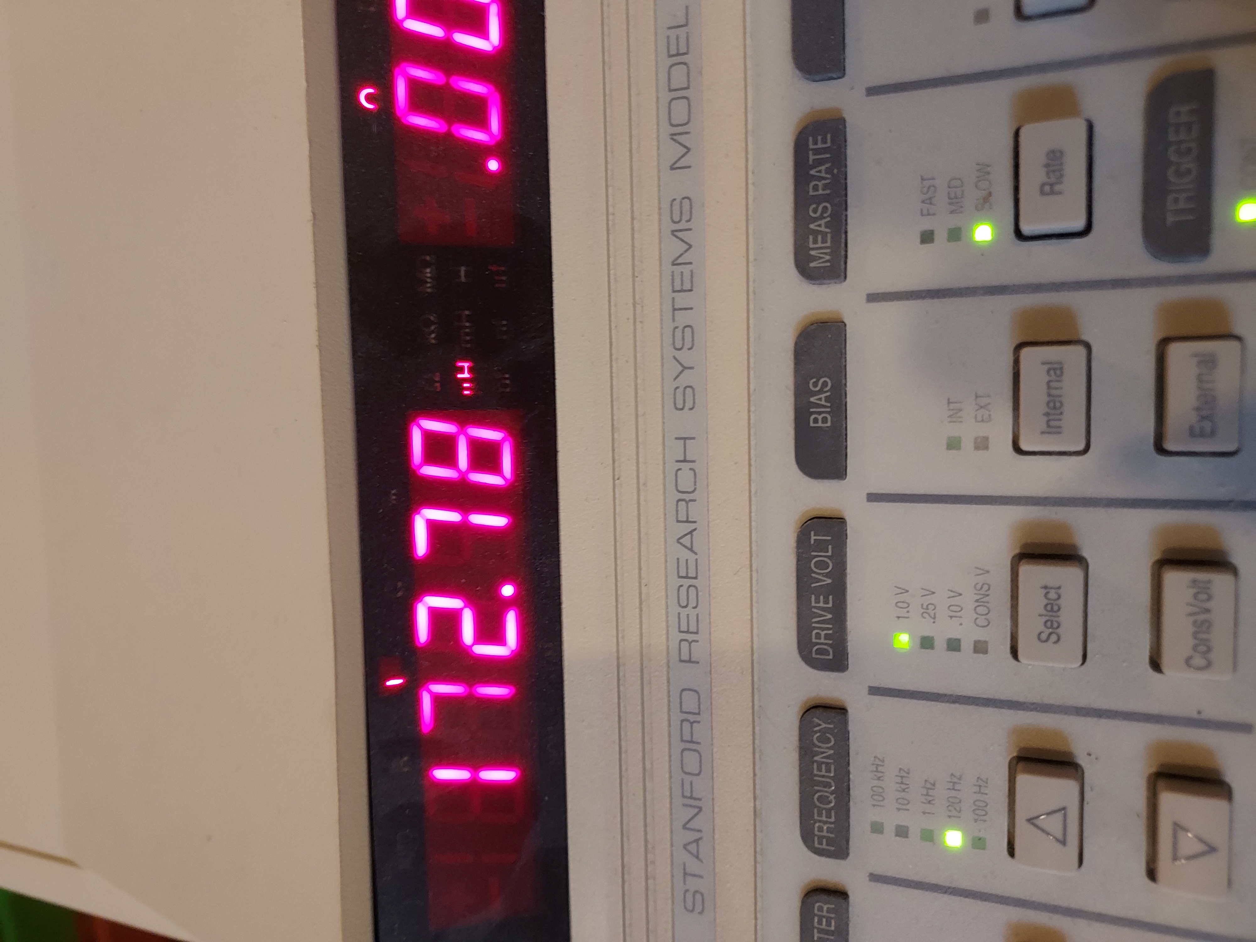
I took a 20mm bobbin (shell from a capacitor), took AWG40 wire (seems like it is AWG40 in that coil) and put 100 turns of it, makin about 2cm-long coil.
Then I put it on my LCR meter (Stanford Research) and tried to extrapolate the results to 17,000 turn coil with the same more or less average diameter.
The Average radius of the RCA coil is 9.8mm, which is the same as the coil i made (10mm).
This is the way the coil looks (right lowe part) and the measurement of L+Q.
As the experiment has shown, the result did not depend on the driving voltage or the frequency (100Hz-120kHz)

Close-up
And the DCR
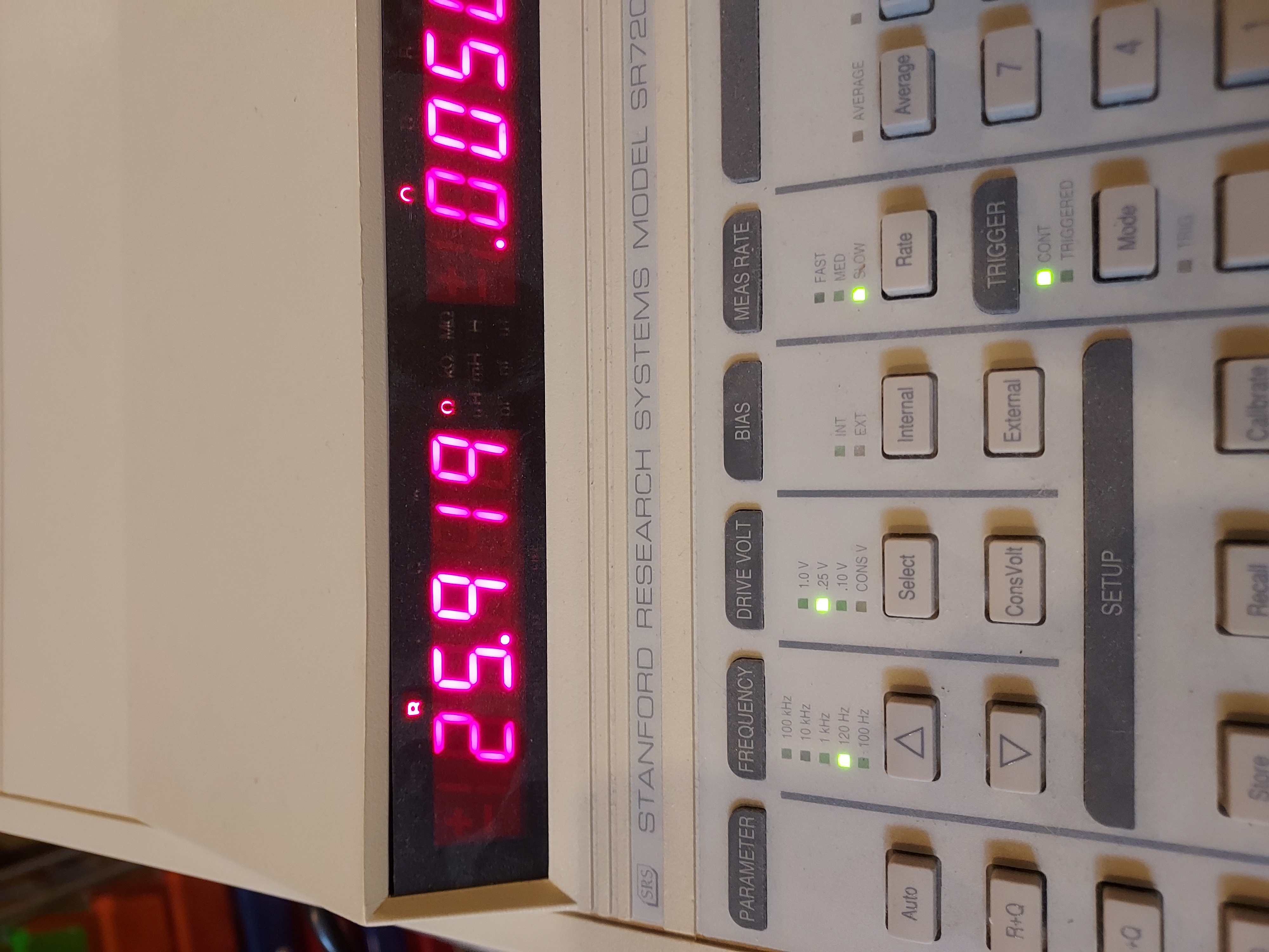
So the 100-turn coil with 10mm radius of the AWG40 wire is 173uH, 26 Ohm.
Now my calculations showed 17,000 turns. This makes it 170-square times the result for L, which is 4.9H and 170 times for R, which is 4,420 Ohm DCR.
Of course this is pretty approximate. I also think the wire might be AWG39 which would account for 4.4K (AWG39 would make it 3.5K which is closer to 3K).
So. I was hoping that the inner end of the AWG40 wire coil that I bought would be accessible, and I'd be able to measure the whole coil inductance, but it is not, so I had to make that coil.
Now, I decided to go to the on-line inductance calculator I used (the one whose image I gave here) and put in my inductance and see what it would give me for my coil.
I put in the diameter, the required inductance, AWG and the length, and it gave me 114 turns (mine is 100) and 25.4 Ohms (mine is 26 Ohms).
Not too bad. When I put my RCA coil's parameters, it is, as before, 2.3H. If it were 100 turns put in, the L would be 133uH.
The other calculator gave me 130uH for my 100-turn inductance, pretty close to 133uH.
So,
1. These calculators are not that far off.
2. Indeed my RCA coil is at least between 2H and 3H.
So I know more or less what they used. A roughly 3H inductance with 3,000 Ohms DCR.
People who do not drink, do not smoke, do not eat red meat will one day feel really stupid lying there and dying from nothing.
Posts: 16,476
Threads: 573
Joined: Oct 2011
City: Jackson
State, Province, Country: NJ
Now to the antenna coil L1. When checking magnetics, soon after started I found the L1 coil was open. Simply by ohming out antenna to GND.
Now, this is how it looks.
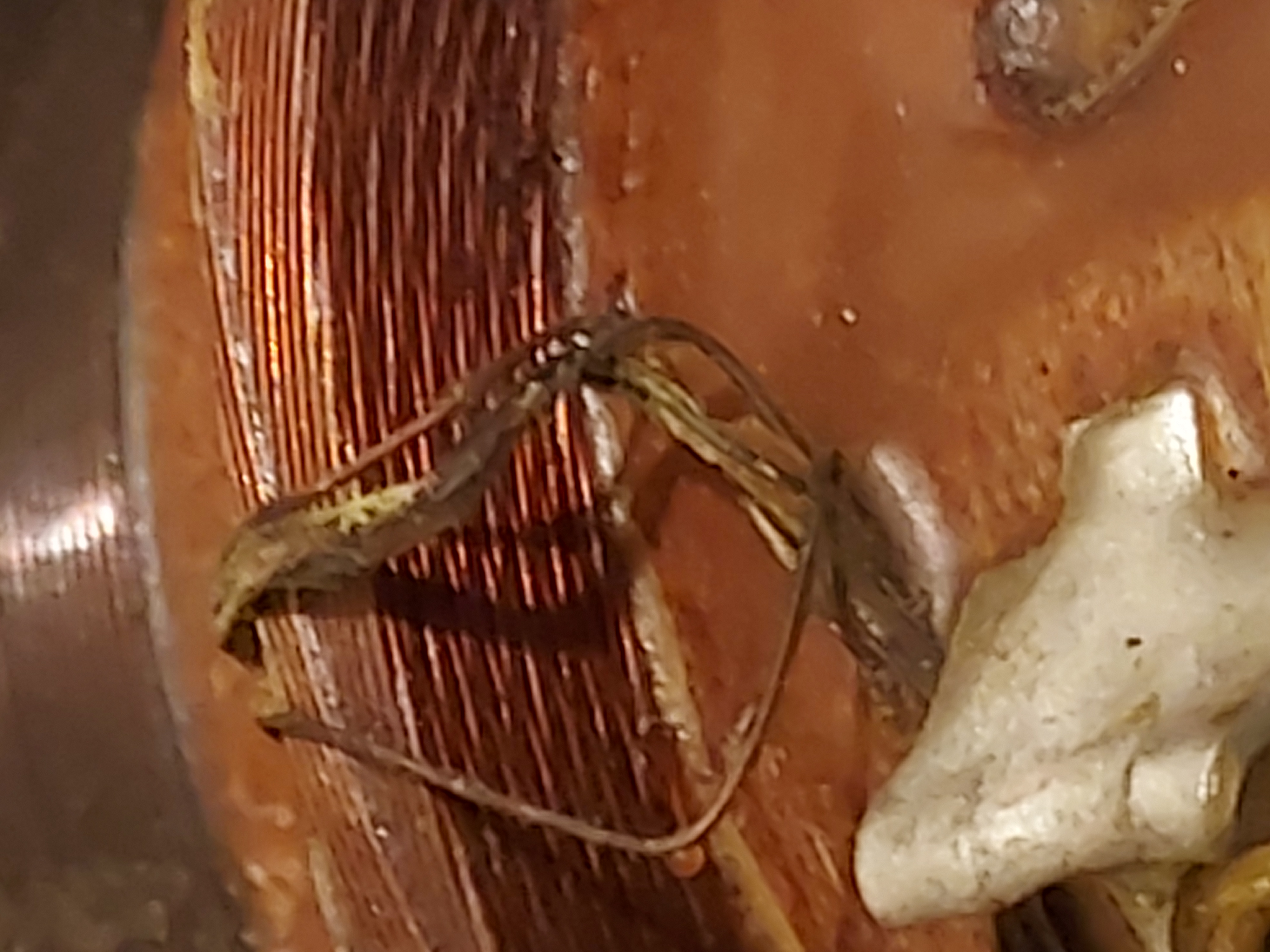
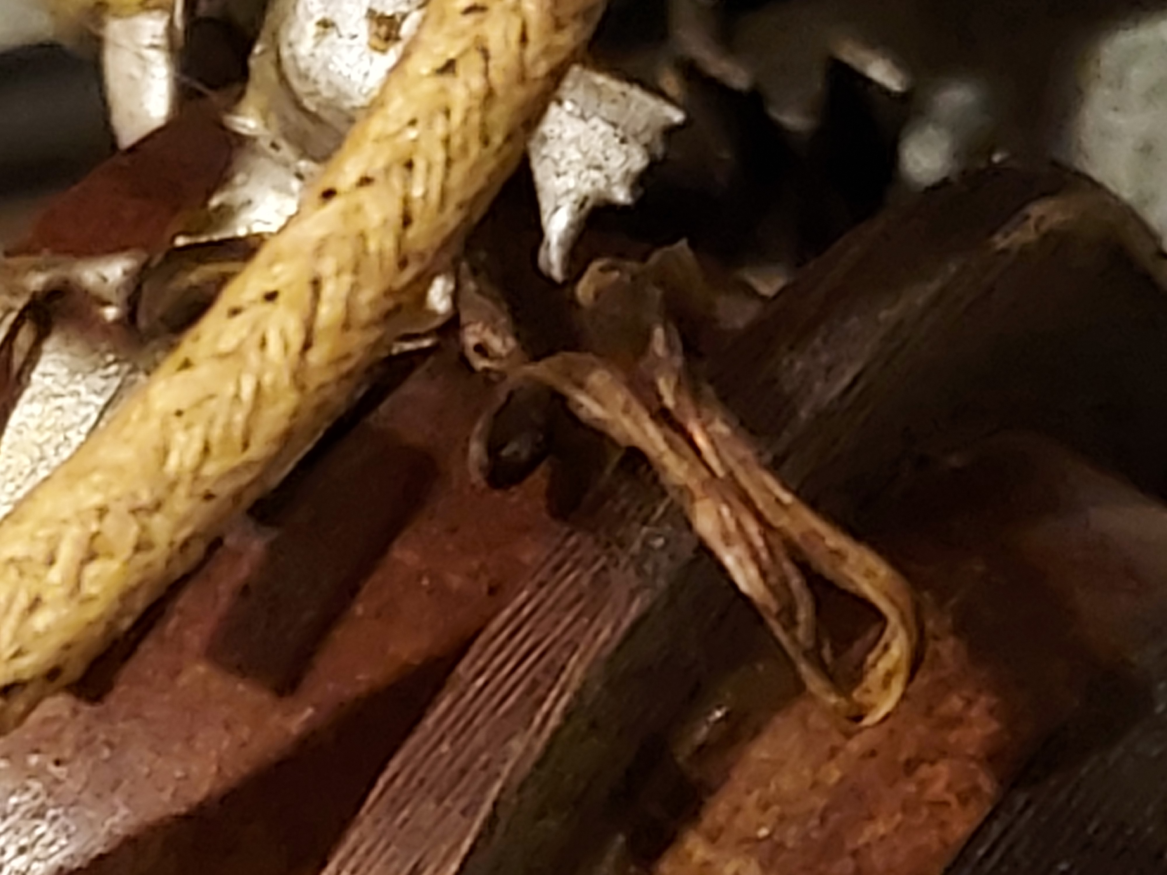
As you can see, the winding is kind of "Universal", but wound with flat 5-filamet (or maybe 6) wire.
I am not sure what happened to this coil, it is open and considering it has a few filaments, all 5 or 6 of them have to be open.
This is what I see:
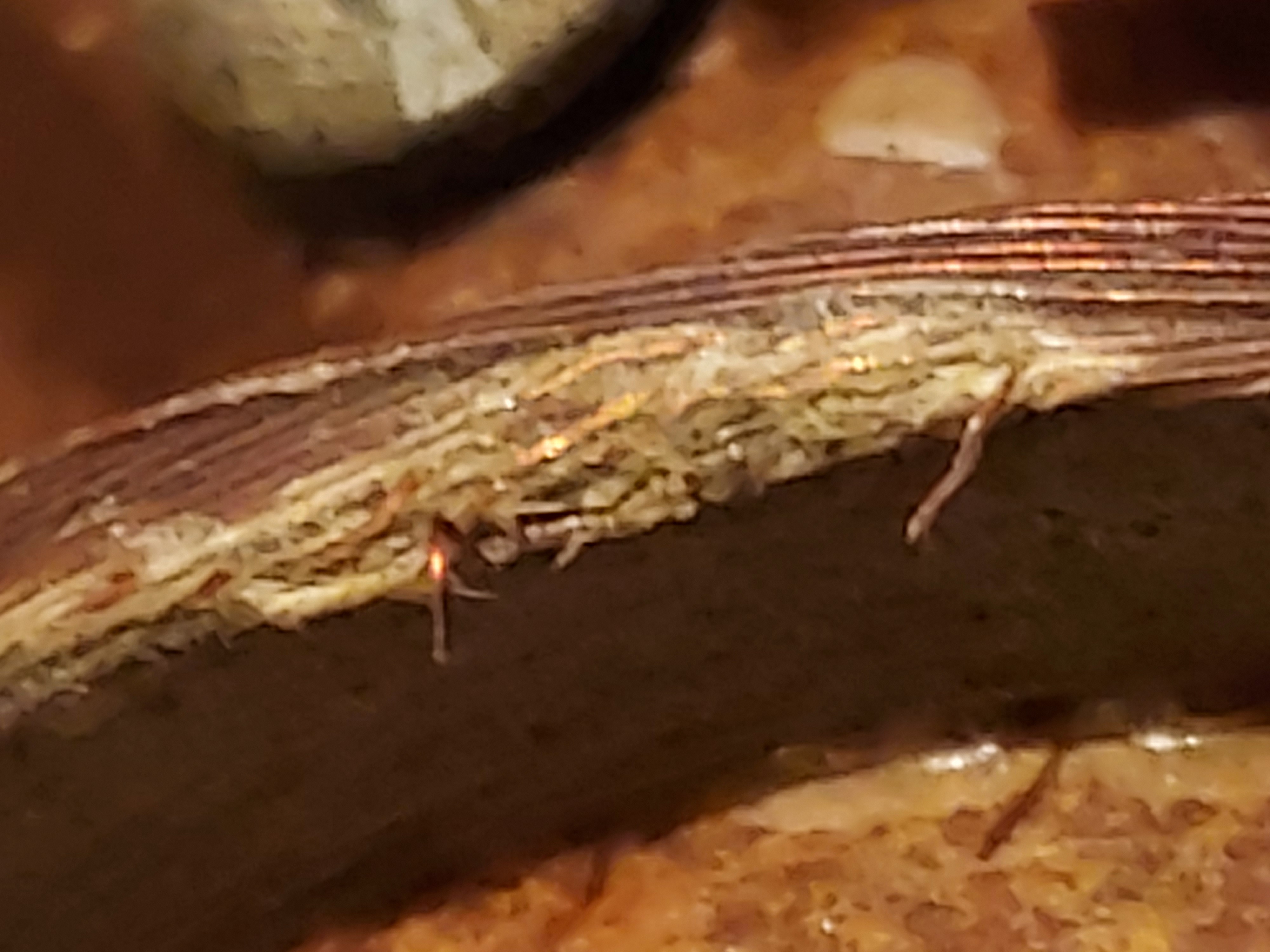
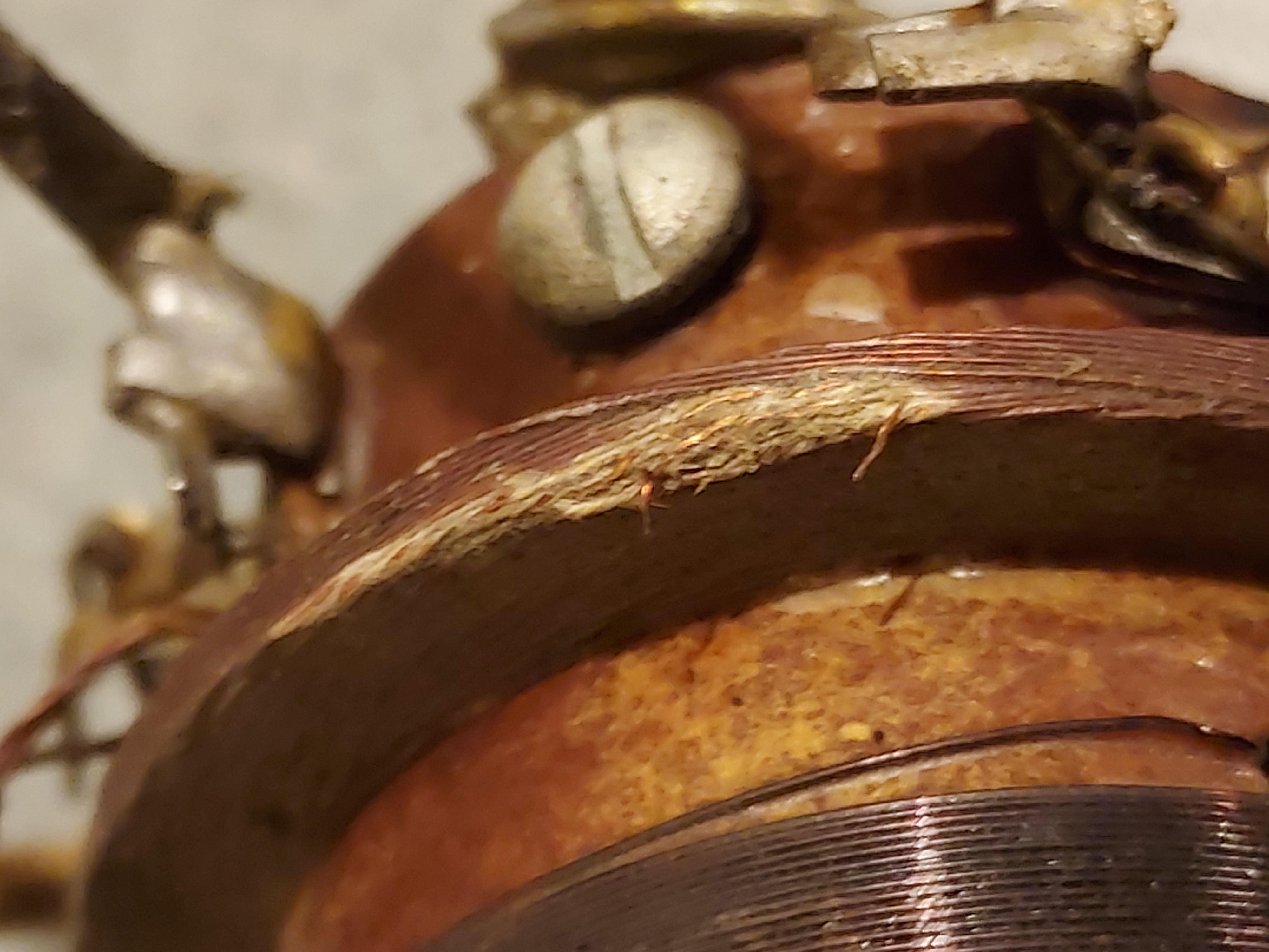
Considetring there are several filaments, I do not think there are many turns there. And I am pretty sure multi-filament flat wire could very well be replaced by litz, which is what RCA was, I think, trying to do. Maybe they did not have litz. Who knows.
But I cannot make "Universal" winding: it is a skill if done manually, and I do not have a tool and am not about t obuild one, as a couple of books suggest.
This is a strictly BC radio, so I am not sure I need to try to reduce inter-layer capacitance greatly, which what Universal winding is for, and litz will take care of whatever skin effect they were trying to deal with.
If anyone has better ideas, I am all ears.
Of course, there is always waiting for a parted radio popping up....
(speaking of which....I will try to look in Oldradioparts, Play Things Of Past. Who knows.....).
PS. Last thought, this is the antenna input coil. It is not, strictly speaking, a tuned coil. The second half is, but the first is not. So if I just make a reasonably similar coil out of litz (same N, and roughly the same geometry), it just might work...
People who do not drink, do not smoke, do not eat red meat will one day feel really stupid lying there and dying from nothing.
Posts: 16,476
Threads: 573
Joined: Oct 2011
City: Jackson
State, Province, Country: NJ
OK, I made a mistake. I thought it is a flat litz. It was not. It was a single wire. They made a small harness from 5 or 6 wires and soldered it as a lead, and them flat-fixed it to the universal-wound coil, so it looked a bit like what I thought it would be. So when I cut the harness and pulled, it was just one wire.
After 30 turns it came off, and there were another 213 turns left, as I found out. Undamaged. So, considering it is a primary, I could've just leave it with 213 turns. But no, I decided to give it an all new winding, which will require 0.11mm (probably AWG38 considering insulation) wire, 243 turns of it, wound between two temporary bobbin flanges which I will make of some paper.
Ok, it is not too bad.
People who do not drink, do not smoke, do not eat red meat will one day feel really stupid lying there and dying from nothing.
Posts: 4,859
Threads: 54
Joined: Sep 2008
City: Sandwick, BC, CA
Mike;
I had a similar issue with the antenna coil on my G.E S-22A, I believe that It had one or two breaks, so I unwound it a bit, spliced the broken piece back on, and wound it back onto the coil. I can see why the later RCA/G.E/Westinghouse sets liked to pack these coils inside cans.
Regards
Arran
Posts: 16,476
Threads: 573
Joined: Oct 2011
City: Jackson
State, Province, Country: NJ
Arran
Yes, and the coil was outside, on top of the chassis, thus being accessible. Thing is, the radio is pristine, no one has tried to repair it.
People who do not drink, do not smoke, do not eat red meat will one day feel really stupid lying there and dying from nothing.
Posts: 1,205
Threads: 11
Joined: Jul 2020
City: Greenlawn
State, Province, Country: NY
I would think that that was mouse damage, but mice usually like to excrete where they eat. 
The cat in the Pixie and Dixie cartoons when I was a kid used to say "I Hate Mieces to Pieces.
Attached below is an article on a Westinghouse RC (RA/DA) receiver that shows the absolute tenacity of the restorer:
"Do Justly, love Mercy and walk humbly with your God"- Micah 6:8
"Let us begin to do good"- St. Francis
Best Regards,
MrFixr55
Users browsing this thread: 1 Guest(s)
|
|
Recent Posts
|
|
Zenith H725
|
| The PSU filter cap arrived today (thank you USPS!) so I will work on that later.
Meanwhile, I have the dial, speaker...EdHolland — 06:42 PM |
|
Philco 610B oscillator wiring
|
| Thanks Terry. After checking my notes I think I recorded about -10v at the 6A7 G4/control grid. The screen grid (G3 &...Tubester — 05:59 PM |
|
The list of my radio & TV collection!
|
| Magical chords of forgotten melodies, old nostalgic music on an old radio... Saturday night blues on the Mid-Waves on an...RadioSvit — 12:20 PM |
|
Philco 42-345 Restoration/Repair
|
| Thank you MrFixr55 the issue with this radio is that the internal coil antenna is missing and there was a wire in its pl...osanders0311 — 11:34 AM |
|
Philco 610B oscillator wiring
|
| Regarding the oscillator circuit which is comprised of the 6A7's cathode, control grid, and screen grid. These elements ...Radioroslyn — 10:33 AM |
|
Philco 42-345 Restoration/Repair
|
| Hi OSanders,
First off, welcome to the Philco Phorum where Phine Phamily-Phriendly Pholks Phull of Philco Phacts and P...MrFixr55 — 08:41 AM |
|
Philco 42-345 Restoration/Repair
|
| Today I've been reading through the site trying to learn more about this radio. I also soldered the lose power cord cabl...osanders0311 — 08:24 PM |
|
Philco 610B oscillator wiring
|
| Thanks David! I do have that same later prodution model 610 schematic. I've also studied the Philco service bulletins fo...Tubester — 08:12 PM |
|
Philco 610B oscillator wiring
|
| Some info from Beitmans says late production. David David — 06:06 PM |
|
Restoring Philco 96
|
| Oh wow! Just found this thread. Brings me back to early days on this phorum. I did a 96 back in 2017. Thread here:
...rfeenstra — 06:05 PM |
|
Who's Online
|
There are currently 2427 online users. [Complete List]
» 2 Member(s) | 2425 Guest(s)
|
|
|

|
 
|


![[-] [-]](https://philcoradio.com/phorum/images/bootbb/collapse.png)


