Philco 42-345 Restoration/Repair
Posts: 63
Threads: 2
Joined: Mar 2025
City: Bristol
State, Province, Country: VA
Hello MrFixr55 sorry to bug you with this but in regard to the wire touch.
"Secondly, yes, touching a long wire to the terminal of the Mixer section of the tuning cap should allow you to tune a station if the oscillator is working. This is the part I meant for Ken's troubleshooting his set, but it could work for you. There are 2 sections to the tuning cap, the mixer / RF and the Oscillator. Usually, the oscillator section is the one closer to the shaft. touch a 25 foot or longer wire to the Mixer section of the cap. Ig you can now receive a signal, then troubleshoot the antenna section of the set. There are antenna coils and the "B" section of the band switch. The "A" Section controls the oscillator."
Overnight the radio was unplugged, this morning I turn it on and nothing but static. I do the wire touch, get a station to tune in and from then on the radio is fine even if turned off or unplugged. It's kind of like jump starting a car battery. It's puzzling since the antenna is pulling in stations.
I see the antenna broadcast transformer is #8 on the schematic, could this be the issue?
Posts: 63
Threads: 2
Joined: Mar 2025
City: Bristol
State, Province, Country: VA
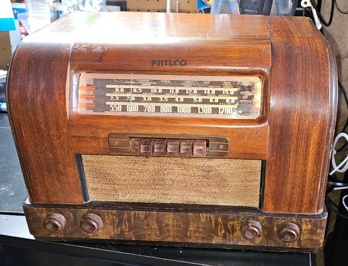
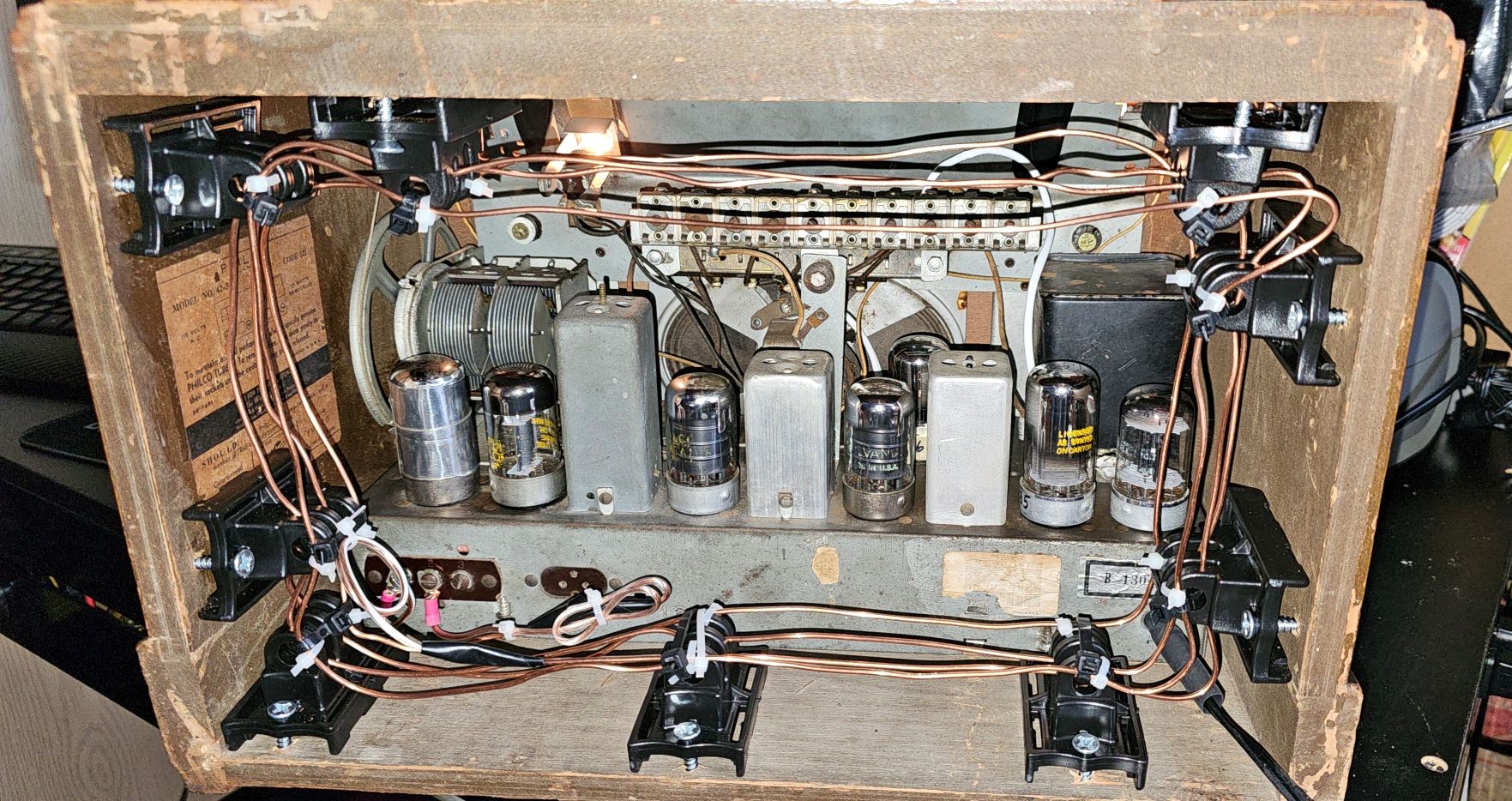
About to go home, a lot better than when I first tackled it. Especially the smell of the old paper capacitors, no antenna and apparently some wrong tubes and prior replacement capacitors. Don't laugh at my antenna  I am glad that it's working though.
Posts: 2,263
Threads: 164
Joined: Jan 2013
City: Westland, MI
Oh boy, nothing is more frustrating than intermittent issues. Try wiggling each tube in its' socket. Loctal tubes are notorious for poor contact with the thin pins. If that does nothing, try tapping different components with a chopstick and listen for changes in the static. You could also re-flow all solder points underneath the chassis to eliminate a possible cold joint. Pay very close attention to the condition of the wiring in the chassis. Rubber insulation breakdown could cause an intermittent problem. Check the easy stuff first, then work your way up. Good luck! Take care, - Gary
"Don't pity the dead, pity the living, above all, those living without love."
Professor Albus Dumbledore
Gary - Westland Michigan
Posts: 63
Threads: 2
Joined: Mar 2025
City: Bristol
State, Province, Country: VA
Thanks Gary and yes intermittent issues are a pain; it was off and unplugged for about 6hrs this afternoon. I plugged it back in and turned on and picked up stations as normal. I will pull the chassis tomorrow and double check the antenna circuit in case I missed something. I've spent so much time on this radio I wish it was mine to really dig into it. I now need to find one for myself especially since I now have a few purchased parts.
(This post was last modified: 07-09-2025, 06:42 PM by osanders0311.)
Posts: 5,652
Threads: 56
Joined: Sep 2008
City: Sandwick, BC, CA
Just a thought, this radio is behaving like the local oscillator isn't starting on it's own, though once started it stays working. I wonder if there is a resistor in the oscillator tank circuit that is misbehaving, or defective mica cap? I had a Northern Electric set where the oscillator would work normally sometimes, and at other times it would not work at the upper end of the dial, it turned out to be a flakey 27K resistor on the 12SA7 mixer-oscillator tube. The local oscillator in this set is a little different in that it uses an XXL tube rather then a pentagrid convertor, but there are similarities. You could try using the eraser end of a pencil to press on various components around the XXL tubes, particularly resistors. It could also be a cold solder joint.
Regards
Arran
Posts: 63
Threads: 2
Joined: Mar 2025
City: Bristol
State, Province, Country: VA
Thank you, Arran I will check around the XXL tubes and double check the resistors in the area. The set has again been off and unplugged since yesterday evening. I just plugged it up and turned on this afternoon and it started playing as when I last had it on. Yesterday I did DexoIT the tuner cap in spots I missed the 1st time.
(This post was last modified: 07-10-2025, 01:52 PM by osanders0311.)
Posts: 2,327
Threads: 23
Joined: Jul 2020
City: Greenlawn
State, Province, Country: NY
Hi OSanders,
I don't think that the 7A7 did damage unless the pins that are not used for a 7A4 / XXL are used as "terminal strips" and even there, I don't think that there is an issue. It is remotely possible that the radio would work with a 7A7 in place in the mixer stage but when I say remote, I mean remote.
Sounds like you are close. If you only got near to the tuning cap without touching anything and, lo and behold, the radio starts playing and stays playing when the wire and your hand are taken away, then somehow, stray capacitance started the oscillator.
Definitely check resistors and capacitors in the circuit, especially those in the cathode and plate of the oscillator. As a last resort, replace the various mica caps. These are the fixed caps between 100pF (100 mmF) and 330pF (330 mmF). These rarely fail compared to the electrolytic and wax paper / foil caps, but they are not failproof.
Also verify that the tuning cap frame is firmly grounded to the chassis at the factory ground point and that there is good continuity between the rotor shaft and the cap frame. There should be a spring contact. Do clean and lube the ball bearings that support the rotor shaft. after 80 some odd years, the grease could be dry and act as an insulator.
Hope this helps
"Do Justly, love Mercy and walk humbly with your God"- Micah 6:8
"Let us begin to do good"- St. Francis
Best Regards,
MrFixr55
Posts: 2,327
Threads: 23
Joined: Jul 2020
City: Greenlawn
State, Province, Country: NY
Hi OSanders,
Some more things to check:
Check with Paul Philco who has this set (If I got his post right). The leftmost tube as viewed from the rear may be the oscillator. Yours has a shield on it. There is no indication on the schematic that the tube should have a shield. In addition, if the shield is supposed to exist, it must be in secure electrical contact with the metal base of the tube which should have continuity with chassis ground..
That 2.2 Megohm resistor that you replaced, was horribly installed during manufacture. Even if not the cause of your problem, it can become the cause of it.
Check voltage on both sides of the 33K Ohm resistor between B+ and the plate of the oscillator. Voltage should be about 160V at Cap 37 and the resistor, and about 70 V between the resistor and tube plate.
If the voltage at the tube plate is really high when the set is not working, then check socket connections, the band switch and connections to the oscillator coil.
+1 on all comments about socket connections and cold solder joints.
"Do Justly, love Mercy and walk humbly with your God"- Micah 6:8
"Let us begin to do good"- St. Francis
Best Regards,
MrFixr55
Posts: 2,327
Threads: 23
Joined: Jul 2020
City: Greenlawn
State, Province, Country: NY
Sorry, OSanders, I just saw your question about the antenna coil. If you are in a rather strong signal area, even an open secondary on an antenna coil shouldn't cause a problem, but may on yours as yours is a 3 band radio. Sorry, sounds like I am walking both sides of the street with this one.
When I was younger I was able to pick up stations on an AA5 (that is the common 5 tube AC-DC radio) that was broadcast band only by connecting a wire to the mixer section of the tuning cap when the loop antenna was missing. On these sets there is no antenna coil, the loop serves that purpose. But even without the "coil" section of the tuned circuit, I was able to receive stations.
In a previous post you said that you didn't even touch the wire to the tuning cap, you merely got near it. This is why I wonder if you managed to "start" the oscillator. So for now, I would stick to the previous troubleshooting tips. Don't be afraid to "poke around", using an appropriate non-conductive tool. Tap the oscillator tube, the tuning cap, the oscillator and antenna coils, the (gulp) band switch and the caps and resistors associated with the oscillator and mixer.
PS, Don't be sorry to disturb me, I'm already disturbed (or so says Ms. Fixr). No, really I and everyone else on the Phorum are happy to help. I am a retired Field Service Engineer for a biomedical company, and had a 45 year career of solving problems (and keeping the promises that sales reps made). My participation in the Phorum and thinking about problems like yours is a workout for my brain and will hopefully keep me sharp. In addition, all of us old-timers want to suck new folks into the hobby. (From the "If I'm going down, I'm taking people with me" department). Seriously, we are all happy to help, there is no silly or stupid question, and unlike other websites, we reallyt want to make people welcome here.
"Do Justly, love Mercy and walk humbly with your God"- Micah 6:8
"Let us begin to do good"- St. Francis
Best Regards,
MrFixr55
Users browsing this thread: 5 Guest(s)
|
|
Recent Posts
|
|
Philco P45-6365 Universal Transformer Instruction Manual
|
| Can anyone guide me to where this may be found?GRG — 03:00 PM |
|
54C Complete Teardown/Rebuild
|
| I don't think that I have encountered a 12Z3 before, curious how it uses one of those but includes a #43, which is a 25 ...Arran — 02:17 PM |
|
HiFi (Chifi) tube amp build - but my own design.
|
| It's the other forum. I'm also in DIY, but mostly read there. Honestly, I kinda jumped into this without much thought to...TV MAN — 10:43 AM |
|
Philco 71 Code 125
|
| Hello,
I am in need of a schematic for this radio. Mine has the three separate circular tube shields and a shadow me...dconant — 08:06 AM |
|
Stromberg Carlson 1500 Squeal
|
| And life just keeps getting more complicated.dconant — 07:57 AM |
|
54C Complete Teardown/Rebuild
|
| Hello Roy,
here is this one
sincerely Richardradiorich — 12:45 AM |
|
54C Complete Teardown/Rebuild
|
| Richard,
Had grabbed it already but thank you just the same. I find myself wanting to find some way to block out the...glyphmon — 12:03 AM |
|
54C Complete Teardown/Rebuild
|
| Hello roy,
here is a link to the schematic .
Sincerely Richardradiorich — 11:54 PM |
|
54C Complete Teardown/Rebuild
|
| Richard,
The Silvertone 2014 also is a transformerless set, so I am incorporating a 1:1 600 ohm audio isolation transfo...glyphmon — 11:37 PM |
|
Preliminary work on wife's Silvertone 2014
|
| Did an alignment today which was interesting. IF alignment went great, almost all was already spot-on. Adjusting on th...glyphmon — 11:35 PM |
|
Who's Online
|
There are currently 2644 online users. [Complete List]
» 2 Member(s) | 2642 Guest(s)
|
|
|

|
 
|








