Posts: 1,106
Threads: 88
Joined: Jun 2011
City: Tacoma
State, Province, Country: Washington
Got my 116B a couple days ago. What fun scrounging all the necessary tubes.
1) Are 6D6's actually a decent sub for 78's? This has had all the 78's replaced with 6D6's.
2) I have no LO on the AMBCB. If I inject the appropriate frequency, it will pass stations through. Interestingly, ALL other bands work pretty well, including LW. Given that all the LO coils look to be in series on this radio, I'm having difficulty understanding how all the other bands can work, but not AMBCB.
3) I'm fighting a problem with the AGC/detector. There's virtually no AGC action at all, even though I've already replaced practically every component in the detector/AGC circuit. If I apply a bias voltage to the AGC bus, it does change the stage gain, but the detector output remains distorted. The voltages on most points are good.
Posts: 1,106
Threads: 88
Joined: Jun 2011
City: Tacoma
State, Province, Country: Washington
Separate issue: The first audio stage is biased somehow to the point where if I turn up the volume (even with a nice sine wave put into it), it's cutting off half the waveform. Doggone if I can figure it out. :/
Posts: 670
Threads: 11
Joined: Sep 2014
City: Bellmawr, NJ
6C6's and 6D6's can also be use in place of 78's,,,from the tube book I have--RCA series RC 16
Posts: 285
Threads: 27
Joined: Nov 2012
City: Tehachapi. California
BrendaAnn
I hope this will help.
Here are some typical voltages for the 77 tube. Look at the class A specs. yours should be similar.
http://www.nj7p.org/Tubes/SQL/Tube_query.php?Type=77
I am curious which half of the waveform is cutoff?
!!!!!!!!!!!!!!!!!!!RESISTANCE IS FUTILE!!!!!!!!!!!!!!!!!!!!!!
/\/\/\/\/\/\/\/\/\
[Image: http://philcoradio.com/phorum/images/smi...on_eek.gif] Chris
Posts: 285
Threads: 27
Joined: Nov 2012
City: Tehachapi. California
And you know that your L.O. problem is most likely going to be in the rotary enigma switch.
Here's my favorite contact cleaner.
http://www.amazon.com/Hosa-Cable-Deoxit-...rds=deoxit
!!!!!!!!!!!!!!!!!!!RESISTANCE IS FUTILE!!!!!!!!!!!!!!!!!!!!!!
/\/\/\/\/\/\/\/\/\
[Image: http://philcoradio.com/phorum/images/smi...on_eek.gif] Chris
Posts: 1,106
Threads: 88
Joined: Jun 2011
City: Tacoma
State, Province, Country: Washington
Looking at the plate of the 1st audio tube, it's strange. Inputting a sine wave at the volume control, I get a soft rolloff of the bottom of the waveform, while the top remains sinusoidal. When listening to an actual radio signal, if the volume is low enough, the waveforms are reasonably good (likely as good as I'm likely to get on AM these days), but if I turn it up even a little higher, the tops of the waveforms drop off in a fashion similar to a sawtooth wave, |\ Obviously the bias is NOT in the sweet spot, but taking voltage readings on the plate and screen grids, I get ~76 and 55, respectively.
Any idea what the grid voltage on the 1st audio should be? I'm getting around -2V.
AGC is getting better. In fact, I can get a good signal on a short wire with reasonable control, but if I connect my longwire it will overload like crazy when tuned to my in house AM transmitter. I'm getting -5 AGC on the RF amp, and around -3 on the 1st IF on a strong signal. I did find a wiring error on the volume control that once corrected made quite a difference in performance.
Posts: 285
Threads: 27
Joined: Nov 2012
City: Tehachapi. California
On the bias voltage it's hard to tell exactly what you should measure. From the database on the 77 -2 volts doesn't sound out of line. With a plate voltage as low as 76 volts it maybe a little much. Your other voltages sound good so from the non linearity on the output either the tube is bad or one or more of the caps in the plate circuit are bad. Try swapping the 77 tubes and recheck all those caps and resistors in the plate circuit.
!!!!!!!!!!!!!!!!!!!RESISTANCE IS FUTILE!!!!!!!!!!!!!!!!!!!!!!
/\/\/\/\/\/\/\/\/\
[Image: http://philcoradio.com/phorum/images/smi...on_eek.gif] Chris
(This post was last modified: 11-24-2015, 04:14 PM by OZ4.)
Posts: 1,106
Threads: 88
Joined: Jun 2011
City: Tacoma
State, Province, Country: Washington
I've replaced every component in both the AGC and 1st Audio circuits. I've tried two different 77 tubes, with the same results. That's why this thing is a bit confusing to me. Given that I found the volume control had been miswired, perhaps I should carefully trace all the other wiring as well.
Posts: 13,776
Threads: 580
Joined: Sep 2005
City: Ferdinand
State, Province, Country: Indiana
(11-23-2015, 12:01 PM)Kenneth F. Besso Jr. Wrote: 6C6's and 6D6's can also be use in place of 78's...
Sorry, but I have to disagree. In my experience, Philcos do not like 6C6 and 6D6 tubes; they want to see 77s and 78s, respectively. Even though the tube books say that 6C6 can replace 77 and 6D6 can replace 78, the Philco sets I have worked on have performed better when they have the tube types they were designed for; that is, 77 and 78. Sometimes it took installing a 77 or 78, as appropriate, to turn a non-working Philco into a working Philco.
--
Ron Ramirez
Ferdinand IN
Posts: 1,106
Threads: 88
Joined: Jun 2011
City: Tacoma
State, Province, Country: Washington
Progress report:
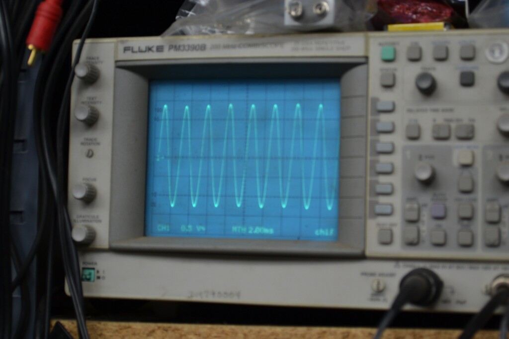
One bakelite block that I didn't get (that I thought I had) solved both the nasty clipping AND the poor AGC action. Block was #79, filtering for 1st audio suppressor and grid bias. Basically, what I think was happening is that at low volume, things behaved more or less normally, but as I increased the volume, the audio signal was modulating the suppressor grid as well as control grid bias, so it was clamping the plate signal by feeding in an out of phase signal.

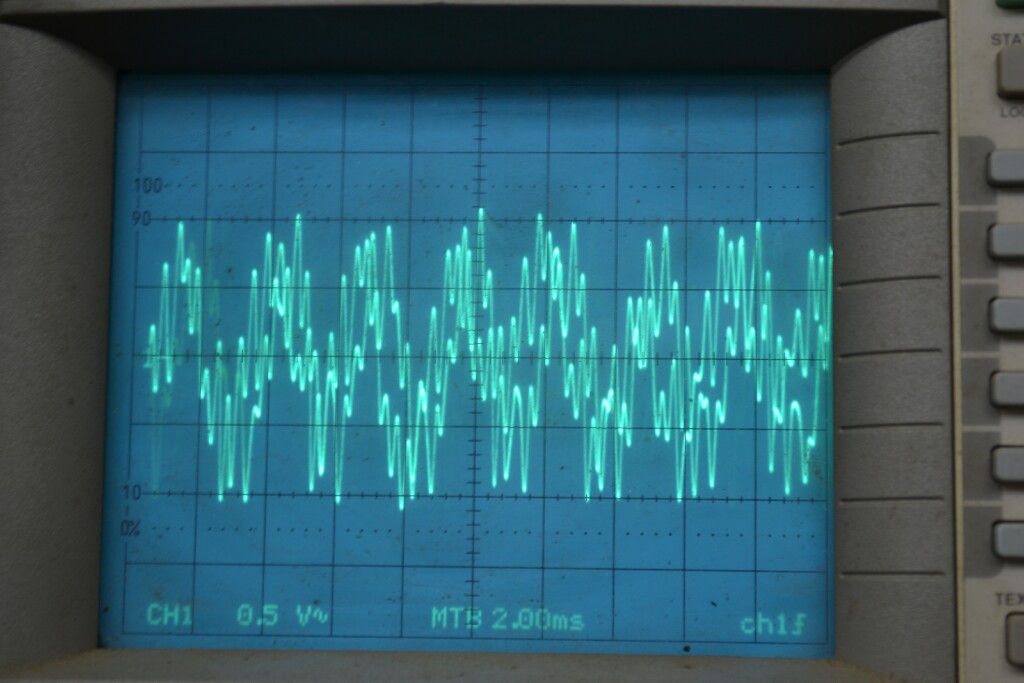
Scope attached to plate of 1st audio, radio tuned to 1700 KHz, generator at 1700KHz with 400Hz tone.

Audio from my inhouse AM transmitter at 1620KHz. (thank goodness for the Police Band on this set)
Audio is now beautiful, though I still have a few paper caps to replace, but mainly these are in the tone control circuit.
LO is still DOA on the AMBCB. All other bands it works great. Still driving me crazy(er). Afraid I'm going to have to pull the LO coil so I can check for problems. Can't see anything wrong with the bandswitch, but that may be just the limited view I have of the LO section of the switch.
Any ideas on that, Ron?
Posts: 285
Threads: 27
Joined: Nov 2012
City: Tehachapi. California
I would try to measure continuity of the osc coil from the grid circuit through the band switch at common wiper point. You should be able to switch the band switch and measure all the different coil sections. This should confirm if it's a coil or a cap that's bad.
!!!!!!!!!!!!!!!!!!!RESISTANCE IS FUTILE!!!!!!!!!!!!!!!!!!!!!!
/\/\/\/\/\/\/\/\/\
[Image: http://philcoradio.com/phorum/images/smi...on_eek.gif] Chris
Posts: 13,776
Threads: 580
Joined: Sep 2005
City: Ferdinand
State, Province, Country: Indiana
I've been looking at the schematic for the 116, as well as the 16 Code 125-126. The front end of the 16 Code 125-126 is very similar to that of the 116, except the 16 does not have a LW band.
Try what Chris (OZ4) suggested above. If the continuity of the oscillator coil is good, then what about mica caps (33B) and/or (33)?
--
Ron Ramirez
Ferdinand IN
Posts: 1,106
Threads: 88
Joined: Jun 2011
City: Tacoma
State, Province, Country: Washington
OK. Here's what I got. I can't get a solid ohms reading on the oscillator coil. If I push on the oscillator section of the bandswitch, I can get it temporarily to settle down, but it won't stay that way.
In other news, the silly thing decided, twice tonight, to start working on the AMBCB. It did so the second time long enough for me to attempt a calibration. I managed to get everything above 1000 KHz to track well, but below that everything was quite high (e.g. 603 KHz tuned in at around 650, and nothing I could do with the low end trimmer would get it any lower. It WOULD, however, bring it UP as high as 800... There doesn't seem to be any fixed capacitance in that part of the circuit that would be affecting it that I can find. But, I'll keep trying.
Posts: 1,106
Threads: 88
Joined: Jun 2011
City: Tacoma
State, Province, Country: Washington
 
Tonight, I seem to have found the issue with the LO. It seems that it was bad contacts in the bandswitch, but not in the section I'd been concentrating on. I now have all bands working and well calibrated. I do need to replace the mounting screws on the LW trimmers, since one of them snapped off while I was cleaning the chassis, and it happened to be the one that grounds those trimmers.
Still need to replace a few caps in the tone control circuitry, and then the chassis is done. Hopefully, when I fire the beastie up tomorrow, the AMBCB will still be working, and I can call it good. Will be posting a WTB ad for a replacement speaker, since the cone on this one is pretty much totaled (amazingly, it still sounds pretty nice... go figure)
Posts: 5,164
Threads: 273
Joined: Nov 2012
City: Wilsonville
State, Province, Country: OR
Users browsing this thread: 1 Guest(s)
|
|
Recent Posts
|
|
Need Help to ID this radio 11 tube Philco
|
| Yes the 16B as morzh pointed out. Specifically its the January 1935 model version of the 16B. There are a couple earli...klondike98 — 11:51 PM |
|
48-482 rear panel help
|
| Welcome to the Phorum, keithchip! How far you take a radio on cabinet restoration is a matter of personal preference. ...GarySP — 11:28 PM |
|
48-482 rear panel help
|
| I've recently finished the internal restoration of a locally purchased Philco 48-482. The cabinet is in ok shape except ...keithchip — 10:28 PM |
|
Need Help to ID this radio 11 tube Philco
|
| Welcome to the Phorum, Ken! Lots of help here for all of your restoration questions. Take care and BE HEALTHY! - Gar...GarySP — 07:59 PM |
|
Need Help to ID this radio 11 tube Philco
|
| Thank you.
I went to your online library and found 2 schematics.
I will download and compare to components!Ken D. — 06:31 PM |
|
Need Help to ID this radio 11 tube Philco
|
| It is a 16B tombstone.morzh — 06:13 PM |
|
Zenith H725
|
| David - sorry, I reread your post and finally saw THD - now the % figures make sense. Thanks for explaining.
The PSU...EdHolland — 06:06 PM |
|
Need Help to ID this radio 11 tube Philco
|
| Hi Everyone,
New member but have been reading this for awhile for tips!
Vaccum tubes were before my time so bear with ...Ken D. — 06:03 PM |
|
My Philco 37-116 Restore
|
| Thank you MrFixR55, I appreciate your comments very much. I do not detect much hum if any so I will be staying with the ...dconant — 05:15 PM |
|
My Philco 37-116 Restore
|
| Hi DConant
Yes, you can replace chokes with resistors. You do stand the risk of increased hum. the solution is to inc...MrFixr55 — 04:23 PM |
|
Who's Online
|
| There are currently no members online. |

|
 
|


![[-] [-]](https://philcoradio.com/phorum/images/bootbb/collapse.png)


