First Radio Resto - Philco 60B
Posts: 13,776
Threads: 580
Joined: Sep 2005
City: Ferdinand
State, Province, Country: Indiana
Solamar Wrote:I did notice that IF tube (should be a 78 per schematics) has been swapped for a 77. Was that a running change or did someone put the wrong tube in?
Not a runnning change - notice it was not mentioned in the comprehensive Evolution of the Philco Model 60 thread. Put the proper tube (a 78 ) in there. Your radio will thank you.
--
Ron Ramirez
Ferdinand IN
Posts: 7,295
Threads: 268
Joined: Dec 2009
City: Roslyn Pa
Did notice that your filter caps are a bit odd. On the bottom normally they would have a solder lug in the center not a wire. Would bet that they have been restuffed with different caps than what is printed on the label. And yes the - side of the caps are not at chassis ground they are at B-. If you where to connect them to the chassis it would short out the negative voltage that the power supply develops from the power transformer hv winding center tap to the bias resistor.
The 77 and 78 share the same pinout but the characteristics are different. Will work but will better with the 78.
When my pals were reading comic books
I was down in the basement in my dad's
workshop. Perusing his Sam's Photofoacts
Vol 1-50 admiring the old set and trying to
figure out what all those squiggly meant.
Circa 1966
Now I think I've got!
Terry
(This post was last modified: 08-10-2016, 08:50 PM by Radioroslyn.)
Posts: 24
Threads: 2
Joined: Aug 2016
City: San Diego, CA
(08-10-2016, 08:37 PM)Ron Ramirez Wrote: Solamar Wrote:I did notice that IF tube (should be a 78 per schematics) has been swapped for a 77. Was that a running change or did someone put the wrong tube in?
Not a runnning change - notice it was not mentioned in the comprehensive Evolution of the Philco Model 60 thread. Put the proper tube (a 78 ) in there. Your radio will thank you.
Will do.
Posts: 24
Threads: 2
Joined: Aug 2016
City: San Diego, CA
(08-10-2016, 08:44 PM)Radioroslyn Wrote: Did notice that your filter caps are a bit odd. On the bottom normally they would have a solder lug in the center not a wire. Would bet that they have been restuffed with different caps than what is printed on the label.
Hah, you are absolutely correct, good eye! I just checked and the bottom of the caps is actually foam rubber with a slit for the wires to come out.
Posts: 24
Threads: 2
Joined: Aug 2016
City: San Diego, CA
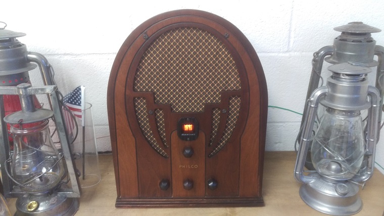
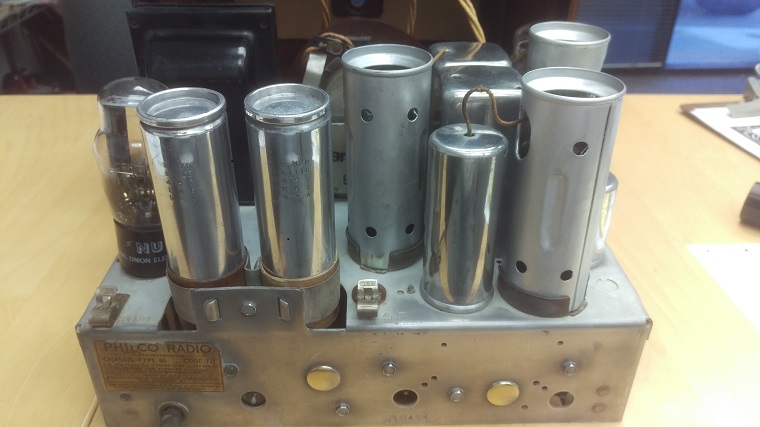
I found a source for some (fairly) original 8mf cans to restuff. All put back together and powered up and it's performing good, but not great.
Tunes in most AM channels that I can pickup with my modern AM radio. There was a fairly bad 60Hz buzz in the background, adding a ground lead to the chassis helped remove about 75% of the buzz but it's still annoying.
My plan is to start working through the bakelite caps now. I plan to do them one at a time and test function (worried about making a mistake that will be hard to trace...).
Is there a logical sequence to replace the bakelite caps?
I have (edited with values found)
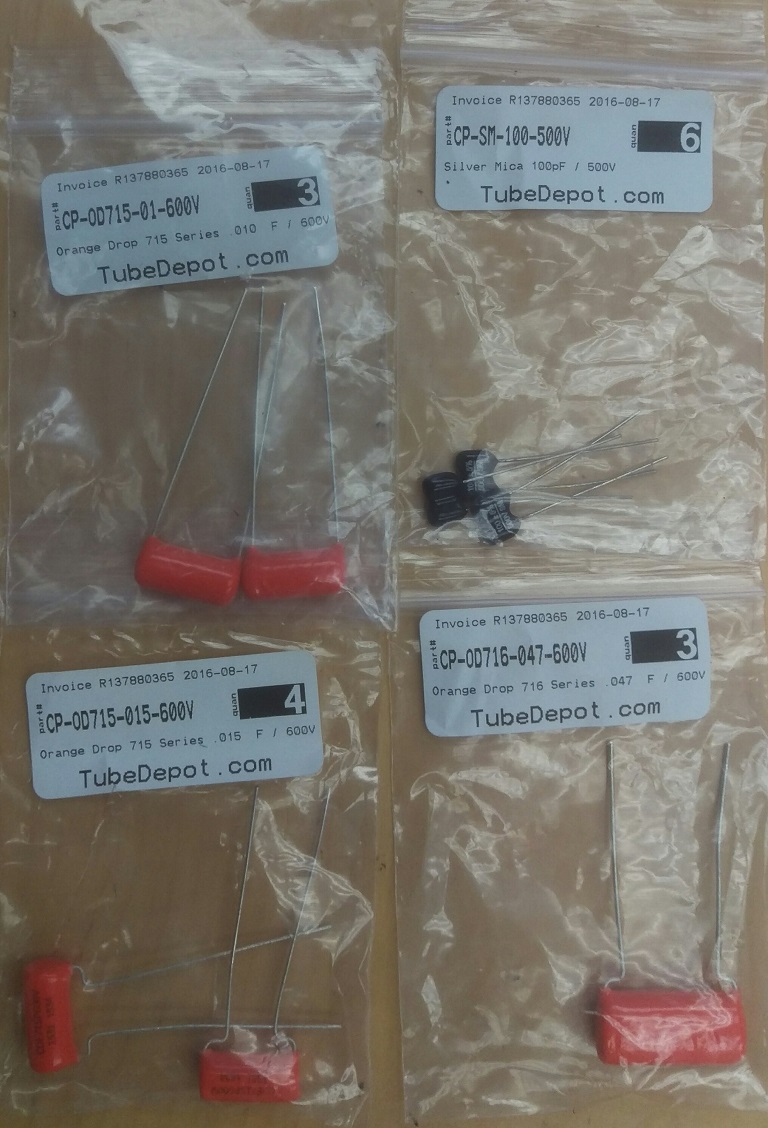
#7 3615-AJ .05 .05 (Will use two .047uf 600V orange drops)
#27 8035-B .00011 .00011 (Will use two 100pf 500V Silver Mica)
#30 3903-AP .01 (Will use .010uf 600V orange drop)
#33 8035-D .00011 .015 (will use 100pf 500V silver mica and .015uf 600V orange drop)
#49 3793-W .015 (will use .015uf 600V orange drop)
From Philcorepairbench I have found the parts list for all except 8035-B and 3793-W. Is there a better list to discover whats inside these?
Also, are there other capacitors besides the bakelites that I should replace?
Thanks for the great info!
Matt
(This post was last modified: 08-16-2016, 07:25 PM by Solamar.
Edit Reason: added found values
)
Posts: 5,160
Threads: 273
Joined: Nov 2012
City: Wilsonville
State, Province, Country: OR
Posts: 24
Threads: 2
Joined: Aug 2016
City: San Diego, CA
(08-16-2016, 06:23 PM)klondike98 Wrote: There is more data here
http://philcoradio.com/phorum/showthread.php?tid=14964
Thank you! So the two I couldn't find are discontinued with replacement P/N's, got it.
Looking at DigiKey, 300, 500 or 1000V Mica caps? General purpose or RF High Frequency?
Posts: 7,295
Threads: 268
Joined: Dec 2009
City: Roslyn Pa
So what number are they on the schematic or actual capacitance ? Not the philco p/n.
When my pals were reading comic books
I was down in the basement in my dad's
workshop. Perusing his Sam's Photofoacts
Vol 1-50 admiring the old set and trying to
figure out what all those squiggly meant.
Circa 1966
Now I think I've got!
Terry
Posts: 24
Threads: 2
Joined: Aug 2016
City: San Diego, CA
(08-16-2016, 07:08 PM)Radioroslyn Wrote: So what number are they on the schematic or actual capacitance ? Not the philco p/n.
I updated post #20 with the schematic number and capacitance.
Posts: 24
Threads: 2
Joined: Aug 2016
City: San Diego, CA
Well this is kinda odd.
I had a 77 tube in place where a 78 tube should have been (I.F.), radio ran fine. I installed a used 78 tube and it motor boats badly. Tube tested a bit low so I put in another 78 that tested good. Motor boats just as bad.
Any ideas what is going wrong?
Thanks,
Matt
Posts: 24
Threads: 2
Joined: Aug 2016
City: San Diego, CA
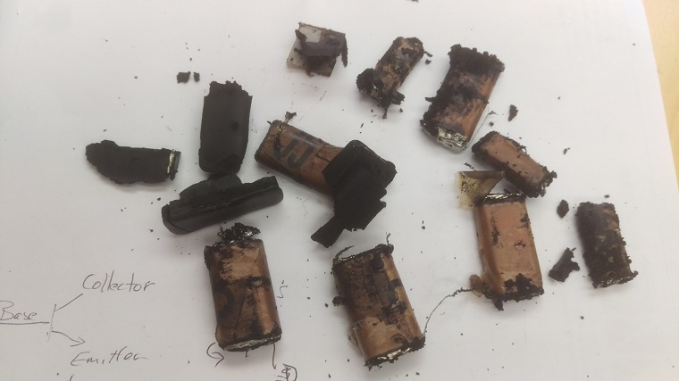
I just finished up replacing all of the capacitors in the bake lite housings. 3903-AP did not make sense, it's replacement part is 3903-OSU which is a .01 uf between pins 1&3. My 3903-AP clearly had the capacitor between pins 1&2 so that is how I wired the replacement.
I must have done something wrong. The radio powers up, all tubes glow and there is a soft hum coming from the speaker. The volume and the tuner dial effect nothing, hum remains constant.
While working on condensor 7 (3615-AJ) I must have broken the solder joint to the resistor leading to condensor 30, easy fix and every other connection appears good.
Any suggestions on areas to start troubleshooting? I'm good with a multimeter, decent with schematics and fair/poor with radio theory...
Thanks for any help,
Matt
Posts: 7,295
Threads: 268
Joined: Dec 2009
City: Roslyn Pa
Check pm box.
When my pals were reading comic books
I was down in the basement in my dad's
workshop. Perusing his Sam's Photofoacts
Vol 1-50 admiring the old set and trying to
figure out what all those squiggly meant.
Circa 1966
Now I think I've got!
Terry
Posts: 24
Threads: 2
Joined: Aug 2016
City: San Diego, CA
Terry (radioroslyn) is not only exceptional at troubleshooting these radios, but a very patient man for putting up with me!
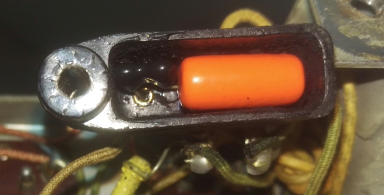
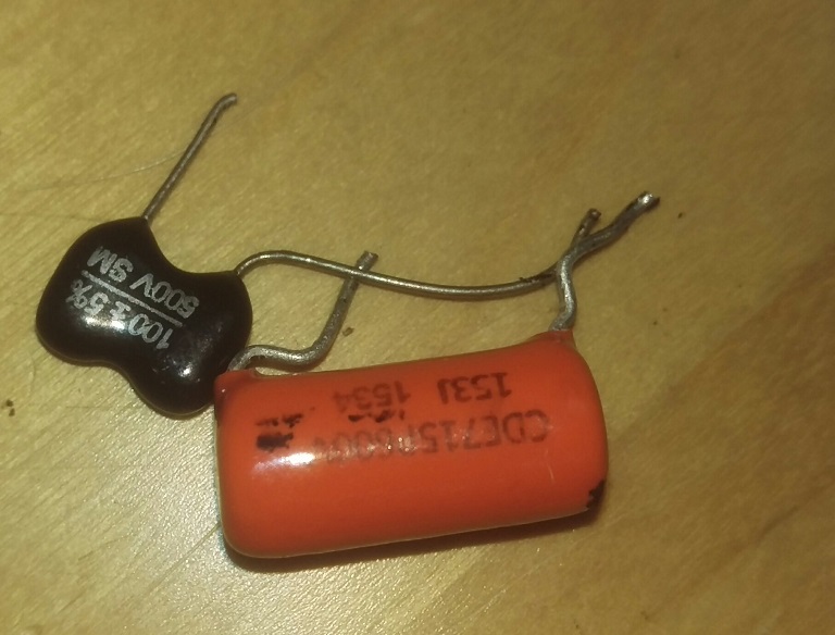
He rather quickly led me to a problem in the #33 bake lite condensor that was sending 160v to the control grid. Turns out that I shorted the legs of the two capacitors inside the bake lite 
The radio is back up and running now (Thank you Terry!). But I still have the motor boating problem. If I tune in a strong channel the motor boating goes away, but it overwhelms most week channels. If I put back in the incorrect IF tube (77) motor boating goes away.
Any advice on tracking down this problem?
Matt
Posts: 7,295
Threads: 268
Joined: Dec 2009
City: Roslyn Pa
Hey Matt,
Glad to help out and get your set back in the pink. Enjoyed chatting with you.
> But I still have the motor boating problem.
You can try adj #26 just a little and see if it calms it down. Add more capacitance to #20 and or add a cap at the bottom of the second IF transformer at the B+ connection, .05 or .1mfd @ 630v is fine. Keep leads as short as necessary to make connections. Also have a look at that 2meg resistor to be sure it's close to 2 megs ( it's part of the avc circuit).
When my pals were reading comic books
I was down in the basement in my dad's
workshop. Perusing his Sam's Photofoacts
Vol 1-50 admiring the old set and trying to
figure out what all those squiggly meant.
Circa 1966
Now I think I've got!
Terry
(This post was last modified: 08-25-2016, 02:40 PM by Radioroslyn.)
Posts: 24
Threads: 2
Joined: Aug 2016
City: San Diego, CA
(08-25-2016, 02:36 PM)Radioroslyn Wrote: Hey Matt,
Glad to help out and get your set back in the pink. Enjoyed chatting with you.
> But I still have the motor boating problem.
You can try adj #26 just a little and see if it calms it down. Add more capacitance to #20 and or add a cap at the bottom of the second IF transformer at the B+ connection, .05 or .1mfd @ 630v is fine. Keep leads as short as necessary to make connections. Also have a look at that 2meg resistor to be sure it's close to 2 megs ( it's part of the avc circuit).
Slight adjustment of Trimmer # 26 and motorboat is gone!
I just finished swapping out the Filter bank capacitors, re-assembled the radio and she's playing beautifully 
Greatly appreciate all the help!
Matt
Users browsing this thread: 1 Guest(s)
|
|
Recent Posts
|
|
Graphics for majestic 1050 dial glass.
|
| Murf;
I found this thread on the ARF, the first photo has a pretty good view of the dial glass.
Regards
ArranArran — 01:12 AM |
|
Zenith H725
|
| hello Ed,
how about that speacial tape used for ducting it's like foil or how about thin piece of
aluminum roof flash...radiorich — 12:19 AM |
|
Zenith H725
|
| Ed;
One material that I have seen, but never tried for this was material for making exhaust gaskets, it's similar to ...Arran — 11:42 PM |
|
Zenith H725
|
| I just remembered, I have some hi temp silicone rubber material which could do the trick. Or a piece of FR4 laminate. Th...EdHolland — 08:39 PM |
|
Zenith H725
|
| The PSU filter cap arrived today (thank you USPS!) so I will work on that later.
Meanwhile, I have the dial, speaker...EdHolland — 06:42 PM |
|
Philco 610B oscillator wiring
|
| Thanks Terry. After checking my notes I think I recorded about -10v at the 6A7 G4/control grid. The screen grid (G3 &...Tubester — 05:59 PM |
|
The list of my radio & TV collection!
|
| Magical chords of forgotten melodies, old nostalgic music on an old radio... Saturday night blues on the Mid-Waves on an...RadioSvit — 12:20 PM |
|
Philco 42-345 Restoration/Repair
|
| Thank you MrFixr55 the issue with this radio is that the internal coil antenna is missing and there was a wire in its pl...osanders0311 — 11:34 AM |
|
Philco 610B oscillator wiring
|
| Regarding the oscillator circuit which is comprised of the 6A7's cathode, control grid, and screen grid. These elements ...Radioroslyn — 10:33 AM |
|
Philco 42-345 Restoration/Repair
|
| Hi OSanders,
First off, welcome to the Philco Phorum where Phine Phamily-Phriendly Pholks Phull of Philco Phacts and P...MrFixr55 — 08:41 AM |
|
Who's Online
|
| There are currently no members online. |

|
 
|


![[-] [-]](https://philcoradio.com/phorum/images/bootbb/collapse.png)


