Hi-Fi tube amp kit from China
Posts: 1,212
Threads: 85
Joined: Jan 2014
City: Annapolis, IL
State, Province, Country: USA
Ok, so I decided to try something - probably crazy. I have been looking at some of the tube amp offerings on Ebay and Amazon from China for over a year. Chi-Fi, or something like that. Prices seemed ok, shipping, and who knows- customs. I found this, or it found me, so after some thought, I pulled the trigger. So this thread will be about my experience with this, good - or bad.
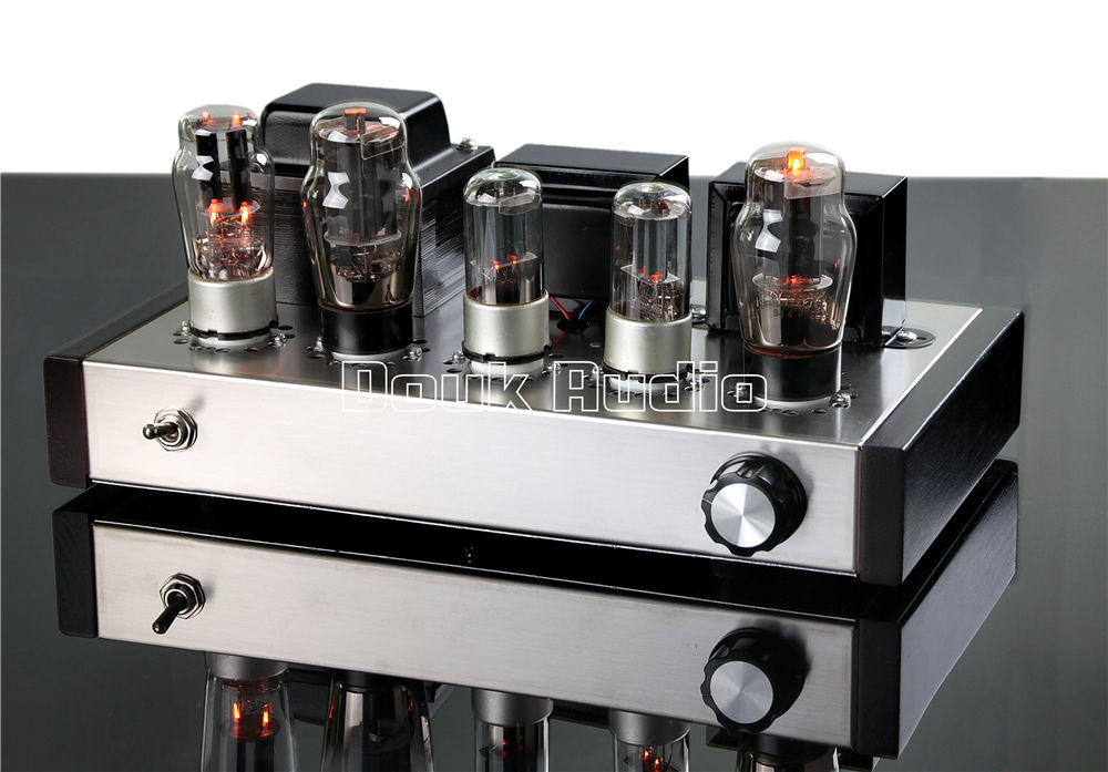
I am starting with something economical to get a feel. I was fascinated with this amp, just a power amp, not much of an earth thumper, but should be adequate for my desk in my office, and maybe a conversation piece. I ordered a Doukaudio single ended amplifier kit. http://www.ebay.com/itm/251524336031?_tr...EBIDX%3AIT
Looks like it uses a European type output and voltage amp tube, kind of like a 6L6G and 6SN7GT.
I could have paid the extra $30 or so and gotten it already built, but (I think) I kind of wanted the kit building experience on one of these. So, I guess now I wait and see what, if anything shows up, and if so, what condition it arrives.
If I could find the place called "Somewhere", I could find "Anything" 
Tim
Jesus cried out and said, "Whoever believes in me , believes not in me but in him who sent me" John 12:44
(This post was last modified: 10-12-2016, 10:52 PM by TV MAN.)
Posts: 16,533
Threads: 573
Joined: Oct 2011
City: Jackson
State, Province, Country: NJ
Yep, lots of those on eBay. A couple of hundred bucks. Not bad.
is it Class A? Looks like it.
People who do not drink, do not smoke, do not eat red meat will one day feel really stupid lying there and dying from nothing.
Posts: 1,212
Threads: 85
Joined: Jan 2014
City: Annapolis, IL
State, Province, Country: USA
It arrived today! Took about 10 days from placing the order to arriving at our house.
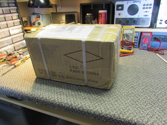
The box looked beat - oh boy ... 
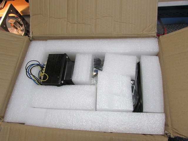
Upon opening I found things packed to survive the abuse of coming halfway around the world 
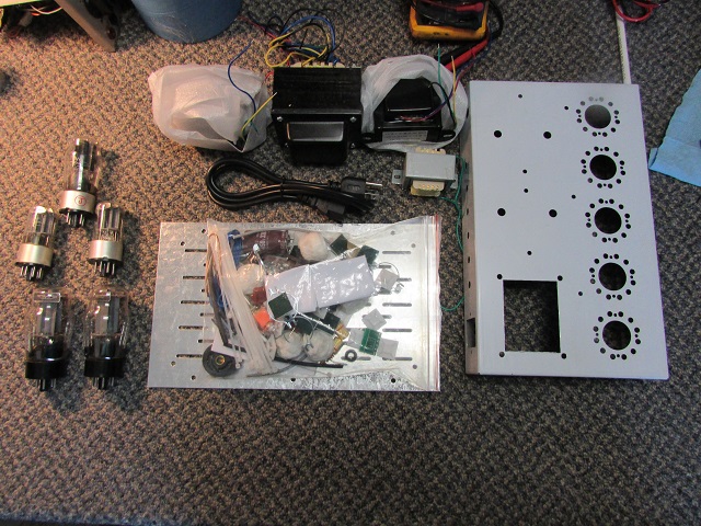
It looks like a kit to me! 
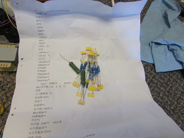
These are the instructions??? 
Ok, so here are my sentiments so far:
GOOD:
I like the idea of NEW for a change.
The chassis is fairly heavy, I kind of expected tinfoil.
Transformers all checked for continuity.
Nothing was ship damaged, tubes are all intact (nothing broken)
The design seems very simple.
Components seem decent quality upon inspection.
Price is very right - still waiting to see if a bill shows up from UPS tho ...
BAD:
Documentation - what documentation???
Only has a small schematic and parts list. I would at least like a diagram and/or picture to go by for component placement.
Can anyone translate Chinese? 
I have requested at least a good quality picture of the completed chassis and a couple of technical questions concerning connection of the power transformer. I guess I will see how good customer support is on this. So far, tho, it seems overall good, worth the money. Not bad for less than $200, and I get to build an AMP kit! 8)
If I could find the place called "Somewhere", I could find "Anything" 
Tim
Jesus cried out and said, "Whoever believes in me , believes not in me but in him who sent me" John 12:44
Posts: 16,533
Threads: 573
Joined: Oct 2011
City: Jackson
State, Province, Country: NJ
Tim, It's gonna be fine.
People who do not drink, do not smoke, do not eat red meat will one day feel really stupid lying there and dying from nothing.
Posts: 1,475
Threads: 69
Joined: Nov 2012
City: Kansas city, MO.
Congrats on getting it in one piece and quickly from where it came.
You might ask around on some of the forums, maybe someone has instructions on the amp. kit you have.
Posts: 1,212
Threads: 85
Joined: Jan 2014
City: Annapolis, IL
State, Province, Country: USA
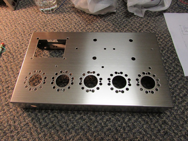
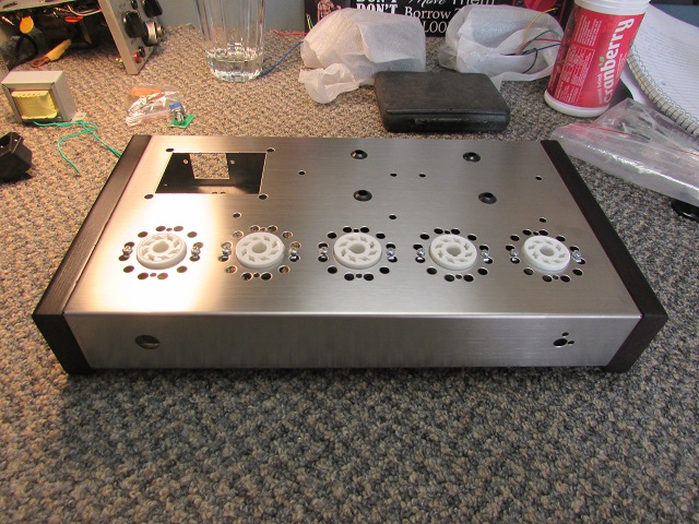
I started assembly. Patience is a really good thing to have to make things look good. The chassis is stainless, so I need to be careful not to scratch with a screwdriver or something. I have been using a picture on the Ebay listing to see how to assemble, position the sockets and such. There are no guide holes on the wood end caps, so you have to mark, drill and thread. They are real wood, not saw dust. I found not to tighten the wood screws too tight or it tries to make things lop-sided. Assemble this part on a smooth surface with a clean rag to keep from scratching.
If I could find the place called "Somewhere", I could find "Anything" 
Tim
Jesus cried out and said, "Whoever believes in me , believes not in me but in him who sent me" John 12:44
Posts: 1,212
Threads: 85
Joined: Jan 2014
City: Annapolis, IL
State, Province, Country: USA
I finally had a chance to get the transformers, binding posts, power switch and input connectors put on.
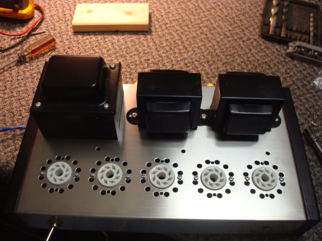
I did learn (the hard way)  not to over tighten the nuts on the speaker binding posts...
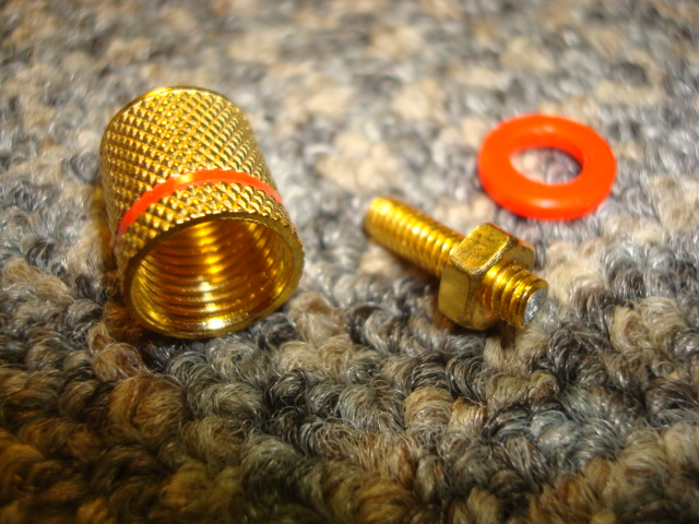
Had to order a set. Oh well..
A couple Q's:
1. This power transformer has 2 primary windings, each at 110v. I assume you connect in parallel for our 120v line? I never got an answer from support when I inquired. Don't know if I should use only one, or both - looks like I connect in series for the 220v.
2. This does not have any line safety caps. Should I add a set of those?
3. There is a green/yellow wire that I assume is ground from the transformer, but it doesn't have continuity to any other lead or even the mounting bolts.
If I could find the place called "Somewhere", I could find "Anything" 
Tim
Jesus cried out and said, "Whoever believes in me , believes not in me but in him who sent me" John 12:44
Posts: 16,533
Threads: 573
Joined: Oct 2011
City: Jackson
State, Province, Country: NJ
Tim
1. I think should be in parallel. Make sure they are not in counter phase.  No blowups just no output either.
2. If it sounds fine and no noise, no caps needed. If you suspect they help, then leave them in.
3.maybe check clwmshell? Gotta connect somewhere.
People who do not drink, do not smoke, do not eat red meat will one day feel really stupid lying there and dying from nothing.
Posts: 1,212
Threads: 85
Joined: Jan 2014
City: Annapolis, IL
State, Province, Country: USA
Thanks Mike.
I never did get any diagram or such from support. I am sure there is a language barrier as well. Anyway, I had been studying the pictures of the underside assembly on Ebay. Not sure I like how it is done. It looks like a lot of components are soldered together in mid air and so on. May be ok, but being a little "old school", I am in the process of drawing out my own "assembly diagram" and instructions, using terminal strips to solder parts to and ground through. I don't think there would be any problem grounding through the stainless chassis (experience welcome), and I am using the vacant #6 pin on the 6L6. I am still refining, and may post my diagram before I start wiring to get opinions on my layout. I think the way I am going to do it will be a lot better than the way it is shown, plus I am taking into consideration future component replacement. 
If I could find the place called "Somewhere", I could find "Anything" 
Tim
Jesus cried out and said, "Whoever believes in me , believes not in me but in him who sent me" John 12:44
Posts: 16,533
Threads: 573
Joined: Oct 2011
City: Jackson
State, Province, Country: NJ
Tim
If you could use terminal strips it will make things a bit more manageable, though mid-air mount was popular way back and works fine. In Russia in fact they used it in 40-s and 50-s, and, instead of solder, they used a welding gun to weld leads together. That was super-reliable. Though the reason it for it being done was pretty mundane - shortage of tin and led 
The leads were also much thicker back then, as we all know comparing old parts to today's ones; so the rigidity was pretty good also.
Mike.
People who do not drink, do not smoke, do not eat red meat will one day feel really stupid lying there and dying from nothing.
Posts: 1,212
Threads: 85
Joined: Jan 2014
City: Annapolis, IL
State, Province, Country: USA
I have spend some "spare time" over the last couple of weeks making diagrams and a checklist (assembly instructions) for this project. I bet I will have spent way more time doing the diagrams and instructions then I will actually building the amp! I have done it in layers to keep things simple. I tried doing it all on a page, but it was way too cluttered, so I did it about like an old Heath assembly book.
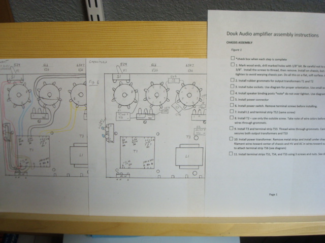
I have some hook up wire ordered from AES, so I don't have to use all blue wire, or get into my expensive cloth covered wire (which wouldn't look right anyway). I did a 'virtual build' following my diagram and check list, and didn't get any 'virtual smoke'. I am going to move to something else until my wire shows up, then tackle this and see how it turns out.
If I could find the place called "Somewhere", I could find "Anything" 
Tim
Jesus cried out and said, "Whoever believes in me , believes not in me but in him who sent me" John 12:44
Posts: 496
Threads: 15
Joined: Mar 2013
City: Weymouth Ma
Great job making good documentation. Gotta wonder at the lack of original though. I am interested in how it all turns out.
Thanks for sharing.
Henry
Posts: 1,212
Threads: 85
Joined: Jan 2014
City: Annapolis, IL
State, Province, Country: USA
I finally had a chance to progress on the construction. I started to change out my broken speaker binding post and found the new ones were slightly longer and of better construction, so I changed out the rest to hopefully avoid future problems. The originals sent with the kit appeared to be a type of pot-metal, but the new ones seemed to be actual metal. They are much better quality 
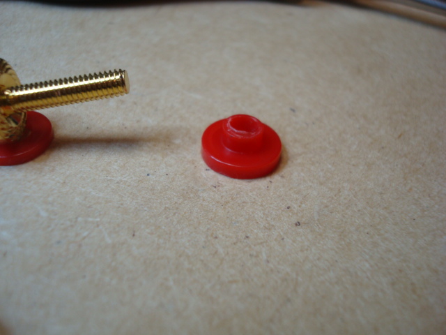
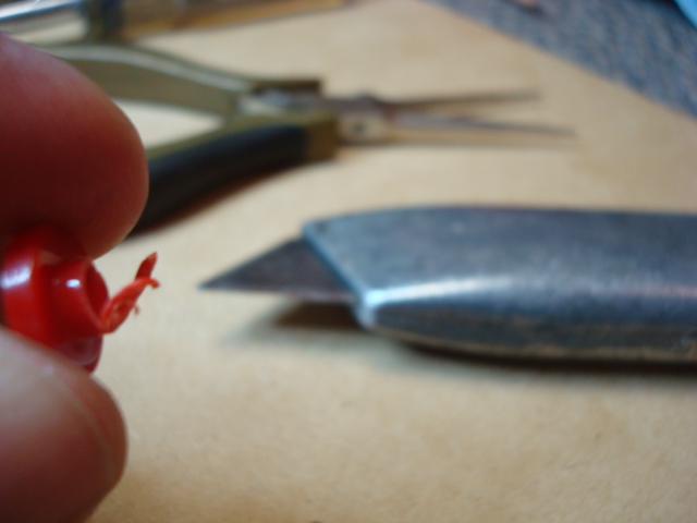
First try, they wouldn't tighten up. The insulator was a little too thick, so I had to glean a little off with a cutter knife. After that, they tightened down nicely. Just a little does the trick. Loose plugs are irritating and can break wires. I recommend to just order a set of these right off if you decide to build this kit yourself. http://www.ebay.com/itm/381197534379?_tr...EBIDX%3AIT
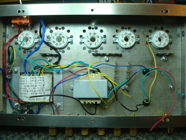
Next is a shot of my terminal strip connectors. I used existing screw holes and carefully attached so as not scratch the stainless steel. The existing screw holes put the terminal strips right where I wanted them. These are something I added to the kit rather than using their method. I had these on hand from AES.
More to come ...
If I could find the place called "Somewhere", I could find "Anything" 
Tim
Jesus cried out and said, "Whoever believes in me , believes not in me but in him who sent me" John 12:44
Posts: 1,212
Threads: 85
Joined: Jan 2014
City: Annapolis, IL
State, Province, Country: USA
I began the wiring. One of my holdups was not having the wire I wanted. The wiring in the kit was all one color and stranded. Terrible! So, I ordered various color, solid wire. I broke everything down into (what I think are) simple, logical steps. I started with the AC input wiring. I found my steps all out of order in this section when I started  , so I redid order as I went through the steps. I added a couple that I had originally planned later in the instructions. I made some corrections and updates. I also neglected to diagram the AC connector, so a few minutes with the Fluke, and I had the terminals figured out. After all this, here is what I ended up with:
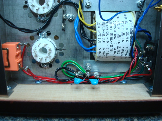
After studying several Hi-Fi circuit schematics I decided to add line safety caps. May not actually need them, but I had them on hand and it seemed like the logical thing to do.
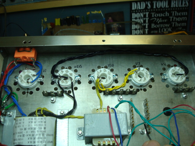
Next, I moved on to the filament wiring. Here, my instructions went smoothly. I will update my diagrams as I made a few minor changes. It's one thing to do it on paper and from pictures, but can be something totally different when it's hands on. I have been following the original posted picture best I can in routing the wire, esp around the small signal section.
After this, I went to the B+ wiring. This went very smoothly. I only made a very minor change in the routing of a couple wires. Not hardly noteworthy.

This is where I quit for the night.
If I could find the place called "Somewhere", I could find "Anything" 
Tim
Jesus cried out and said, "Whoever believes in me , believes not in me but in him who sent me" John 12:44
(This post was last modified: 12-17-2016, 01:00 PM by TV MAN.)
Posts: 16,533
Threads: 573
Joined: Oct 2011
City: Jackson
State, Province, Country: NJ
Tim
I noticed Y-caps under the chassis; some advice: take an MOV, as large as possible, for 250V, and solder it in parallel from line to neutral. Will keep the power side from being fried by surges.
People who do not drink, do not smoke, do not eat red meat will one day feel really stupid lying there and dying from nothing.
Users browsing this thread: 2 Guest(s)
|
|
Recent Posts
|
|
Model 80 Antenna Issue?
|
| You are kind of on the right path. You can touch the grid cap of the Detector/Oscillator 36 tube. I'm expecting a respon...RodB — 08:48 PM |
|
Looking for any info: 1977 Ford-Philco Console Hi-Fi Turntable and Radio
|
| Welcome to the Phorum, PittsburghToast! I found an old thread that my interest you regarding the quality and worth of P...GarySP — 08:48 PM |
|
Looking for any info: 1977 Ford-Philco Console Hi-Fi Turntable and Radio
|
| Welcome to the Phorum!
:wave:
We do not have anything on that unit in our digital library. There is a Sam's Photof...klondike98 — 08:47 PM |
|
Model 80 Antenna Issue?
|
|
I’ve replaced all the caps and resistors and the radio is working but minimal volume unless I put my hand near the re...Hamilton — 08:24 PM |
|
Looking for any info: 1977 Ford-Philco Console Hi-Fi Turntable and Radio
|
| Hi there! this is my first time posting. I recently picked up this Ford-Philco Console record player and radio at a yard...PittsburghToast — 07:28 PM |
|
philco predicta
|
| I found that where I have the 140v B+ there is 50v and the tuner receives 235v through the orange cablecgl18 — 04:14 PM |
|
Philco 91 code 221
|
| Chassis grounds thru rivets is another good place to look. Oh and the stator screws on the tuning cap where the leads at...Radioroslyn — 08:11 AM |
|
Philco 91 code 221
|
| Dirty tube pins and socket, cold solder joint, stray tiny strand of wire, clean the entire area around the oscillator tu...RodB — 08:43 PM |
|
Philco 91 code 221
|
| I have been restoring one of these sets and switched it on yesterday. It didn't exactly spring into life, but after a co...Philconut — 08:26 PM |
|
Philco 50-925 antenna connections
|
| That's super. Glad to hear you figured it out. Paul.Paul Philco322 — 11:11 AM |
|
Who's Online
|
There are currently 1357 online users. [Complete List]
» 4 Member(s) | 1353 Guest(s)
|
|
|

|
 
|


![[-] [-]](https://philcoradio.com/phorum/images/bootbb/collapse.png)


