Posts: 182
Threads: 5
Joined: Feb 2017
City: Cedar Rapids Iowa
Today I stumbled onto something that I want to run by everyone in hopes that someone can help me understand what is happening. This may be a little long-winded...sorry, I just want to give as much info as I can.
I decided to try to eliminate the function switch as the problem. It really acts like something isn't being connected properly when switched to FM. So I connected jumpers to the appropriate places...9 jumpers in total. Eventually, I decided to take off all but 3...those that switch in the FM oscillator circuit. I've not ruled out the switch as a problem completely, but I really don't think it's the problem.
But in the process of doing this testing I thought a heard a faint station on the speaker, so I held it up to my ear and it was a station, 104.5FM. The dial was all the way at the low end so I scanned it to the top. I received the same station all the way up the dial and it was strongest at the top end. At full volume it's loud enough to hear it from a few feet away, and distorted.
I had my generator on and when I changed the frequency the signal went away. So I did some experimenting and found that I could receive 3 or four stations by tuning my generator to different frequencies, and the tuning condenser on the radio didn't change the tuning at all.
Ok, now the interesting thing. I received 104.5 when my generator was set to roughly 95.4, and I received 102.9 when my generator was set to roughly 93.8. In each case the difference is roughly 9.1mhz which is the IF frequency on the radio. So it seems like the generator is acting as the local oscillator, and the tuning on the radio is ineffective.
Can someone explain to me what is happening and what I should do next?
Thanks,
Rich
Posts: 1,824
Threads: 114
Joined: Jul 2014
City: Sneedville, TN
If your FM IF frequency is about 910 khz, look at the difference between what you were hearing and where your sig gen was set. Looks like the sig gen was acting as a local oscillator. This may well mean that the local oscillator in the set is not working on FM. I'd look into that situation. If you have an O scope, check the local oscillator output, and then the wiring from the local oscillator to where it mixes with the received RF in the set. If it is all done in one tube, and things are working on the AM bands, then look at the wiring that pertains to the FM band, including the band switch which may well have a bad contact in that position, or the wiring to that switch may have a problem.
(This post was last modified: 02-04-2019, 06:37 PM by mikethedruid.
Edit Reason: fix error
)
Posts: 182
Threads: 5
Joined: Feb 2017
City: Cedar Rapids Iowa
I took a few days away from the Philco to work on restoring the Jackson 106 signal generator I picked up but now I'm back to working on the Philco. I don't know what has changed since the last time I worked on it, but now I can receive FM signals by tuning the tuning condenser, without the signal generator acting as a local oscillator. It's another step forward, but the stations I receive are still weak and distorted. I've re-done the FM alignment and tried to set the oscillator so that I get stations at the proper place on the dial. But when I set it where I think it's right, many of the stations I receive are in the right place, but I also receive stations at the wrong end of the dial. For instance, I can get 104.5 basically where it should be on the dial, but then I tune up to around 105.5 or 106 and I receive a station that's supposed to be at the other end of the dial, around 88. So, there's still a lot of work to do. If any of this triggers some ideas let me know!
I've been working with my SDR (software defined radio) more and I'm getting more comfortable with it. I don't have the proper SMA adapters yet so I just created a small probe from a piece of wire and made a small coil at the end.
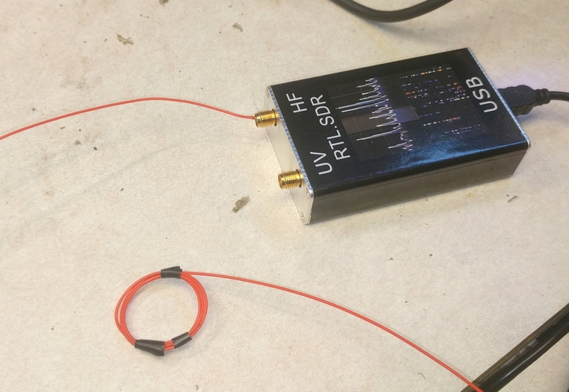
The software for these things allows you to use it as a spectrum analyzer. By inserting the coil near the local oscillator I can see it on the spectrum analyzer display. It works beautifully for AM. But for FM it changes the oscillator frequency when I place the coil near the FM local oscillator coil.
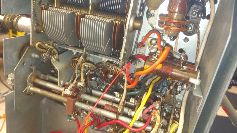
Still, I can see what I think is the local oscillator. It's about where I would expect it to be and moves when I tune the radio. But I also see a signal that's about the same strength as what I think is the local oscillator, but it moves in the opposite direction! So when I tune up the dial, this signal changes to a lower frequency...odd.
My thinking is that the local oscillator is running, but it's weak. I'll keep researching. Thanks for any and all help!
Rich
Posts: 124
Threads: 17
Joined: Jan 2018
City: Kingsville Ohio
If you could show a picture of your computer screen with the results. I've never seen one of those and am interested in getting one if it would help with my troubleshooting. Lord knows I need it!!
Posts: 182
Threads: 5
Joined: Feb 2017
City: Cedar Rapids Iowa
Here you go:
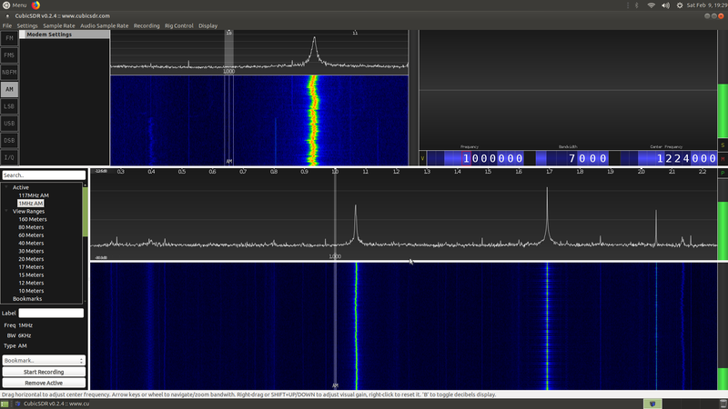
The spike in the center spectrum display that is just under 1.7MHz is the AM local oscillator.
Better yet, here is a link to a video:
https://drive.google.com/file/d/1R67VDxu...sp=sharing
You can see that it starts at about 980kHz, which would mean the radio is tuned to 525kHz, and ends at about 2150kHz, which would mean the radio is tuned to 1695kHz.
I wanted to also record the FM local oscillator, but of course I couldn't get it to display on the SDR. I swear, this thing acts different every time I work on it!
Rich
Posts: 124
Threads: 17
Joined: Jan 2018
City: Kingsville Ohio
Thank You Rich It obviously tells you the oscillator is working but what else does it tell you?
Just trying to learn some stuff.
Dick
Posts: 182
Threads: 5
Joined: Feb 2017
City: Cedar Rapids Iowa
Hi Dick - Right now that's all it tells me...I'm just trying to learn myself! It tells me that it's running, and at what frequency it's running (assuming the SDR display is accurate). The SDR was not created for this purpose but I think it can be useful.
Rich
Posts: 816
Threads: 25
Joined: Mar 2014
City: Louisville, KY
Craigeek,
That is EXACTLY why I am dealing with what I'm dealing with on my 39-6 : I , too, "thought" those tiny wires ( with their microscopic , fraying insulation), was just debris, and PULLED ONE OFF! . . . Turns out it was one of the two leads of the secondary winding of the IF transformer. I just didn't see it well.
So, to concur with the others, yes, ... be VERY careful not to damage those tiny coil wires.
Jake
(This post was last modified: 02-10-2019, 12:57 AM by Jake Blake.
Edit Reason: name correction
)
Posts: 182
Threads: 5
Joined: Feb 2017
City: Cedar Rapids Iowa
Hey Jake - I'm having trouble relating your post to my thread...can you enlighten me?
Also, thanks for correcting the name, but it's still wrong ;) It's criageek. cr for Cedar Rapids. ia for Iowa. geek for...well, I'm a geek!
Rich
Posts: 641
Threads: 48
Joined: Mar 2017
City: Gap Mills Wv 24941
Rich,
im gonna rattle off a few thoughts, & share a few things that were odd ball for my past repairs and hair pulling events.. might help and it might not.
not that i can help but i can say a few things that hit me as i think of them.. your latest FM swagging from left to right and not being consisntent mirrors exactly what happened to me on a recent Zenith am/fm set yet my root cause cant apply to you because mine is slug tuned..... with a metal elevator plate over top the am tuning cap. my root cause was a previous repair man tried to compensate for something,, and do a repair but the pulley that drives the FM cam and shaft was installed many many degrees out of wack... plus it was missing a tension spring.
ive been reading this thread each time to keep up to date since day one.
-just because you see what looks to be a "domino" cap doesnt mean its a capacitor. In my Zenith am/fm set it appeared to look like a domino cap but it is a 25ohm resistor.
-are you absolutely positive you are work from the correct code & run number for your philco?
I started off working on my 46-1226 and discovered that only by close examination of the removable tuning chassis,, some of the resistors were totally not matching the schematic i had ,, so i ordered the correct prints. this may be a stupid question but i digress.
-are you sure any of your loctal sockets are not failing due to carbon trace issues?
-based on your most recent couple pages of posts,, how do you know for a fact somebody did not fiddle with the tuning of the FM stuff. you described most recently that your able to manipulate things to get faint FM to happen with the aid of the signal gen but the stations dont follow the knob properly... and your fm is mostly if not properly addressed as inop.
-once on a radio i got it to *finally work* but when i mounted in the chassis, it would fail within a few minutes. i found that if i did not tighten down the mounting screws really tight, the set works,, so that means that mounting the radio into its cabinet was "twisting" the radio chassis. there must be a random cold solder joint somewhere but i decided to just document it and let it go till some day down the road.
-on a radio one day i finally solved crackle and poping that would occur after about 5min. it ended up that from the vol control there was a shielded wire. this shield was soldered to the chassis in a few places along its path. bypassing the shielded wire with a replacement solved this issue. root cause is that over a period of time, the insulation on the wire inside the shield was eventually arch flashing due to a insulation crack or something. over time i would experience automatic lowering of volume until a point where cracks and pops were all that could be heard. this symptom was appearing to be silver mica issues but that ended up not being the case.
-i have seen a few newer pics and i would not allow any original resistor to remain in the set. you can not be sure there isnt a microscope crack or some fault with a particular resistor contributing to the FM osc section 3 if i am following you on this band sw location your on now.
-some radios manuals have a table that basically gives you the expected voltages on each pin,,, my 46-1226 code 125 run 3 doesnt have this like many other radios do.
-if you can get some faint FM to come in,, can you make an FM adjustment on one of your IF cans and make the station go away ,, then bring it back with your non conductive adjuster tool???????? can you do this same step for all the other FM adjustments??????
(you'd have to mark your original locations first so you can put the adjustments back close to where they were.)
-have you tried to to make an FM antenna and get it outside? i made a few lately they are real easy.,, but must be a specific length.
-i see you have new tubes... spares are good.
-are the smaller copper looking blades on your tuning cap dedicated to the FM tuning? if yes, i noticed on my radios there are two or three adjustments there,, on my zenith these small mica caps really made the big difference on getting FM back into good harmony. i ended up abandoning the FM alignment instructions because i discovered that adjusting just these caps fixed made FM come around loud and clear. This was good because it told me that my IF can adjustments were somewhat ok ,,, the little caps near the tuning cap,, there are two that made things better, one adjusted the station to the left or right of where my needle was,, the other adjustment seemed to increase the reception. I discovered that if i just adjusted my needle to a particular station like fm99,, where i do have a station,, i adjusted by ear either of these small caps till the station agreed with my needle location. I went up to 106.9 and repeated,, went down to FM 88 and it was dead on.
sorry for the long babble,, looking forward to what you find.
scott
304 772 3411
(This post was last modified: 02-10-2019, 02:14 PM by jcassity.)
Posts: 182
Threads: 5
Joined: Feb 2017
City: Cedar Rapids Iowa
 02-10-2019, 02:16 PM
WOO HOO!!
https://drive.google.com/file/d/1j5hlnXt...sp=sharing
The latest problem I had was self-inflicted [Image: http://philcoradio.com/phorum/images/icons/sad.gif] When I received the replacement IF (I've been calling it the 3rd IF, the Philco documentation calls it the AM detector/FM discriminator), I just tacked the wires because I knew I would remove it to clean it and replace the wires if it worked. It did work, so I removed it to do the cleaning and wire replacement then soldered it in permanently. Well, it turns out I reconnected one of the wires to the wrong terminal [Image: http://philcoradio.com/phorum/images/icons/shocked.gif]. I made the correction and boom! Lots of FM! To me it sounds a little distorted, and the tracking is off. When I set it according to the procedure and get the high end lined up with the dial, the low end is off...I receive a 92MHz signal at about 91. Also, there is at least one station that is in completely the wrong place. I'm receiving 90.9 at the top end of the dial, at about 107 or 107.5.
I'd like to do the part of the FM alignment that involves adjusting the coils (FM aerial, FM RF, and FM oscillator) to see if that helps with these issues.
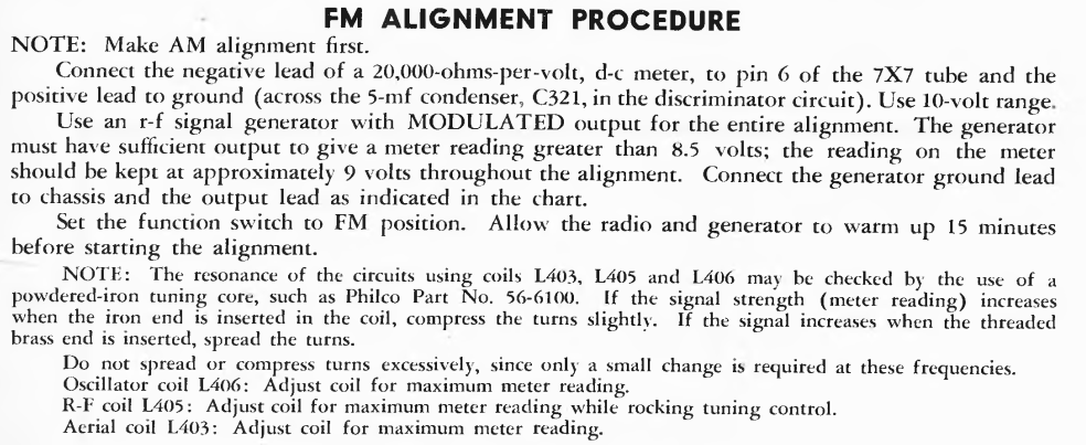
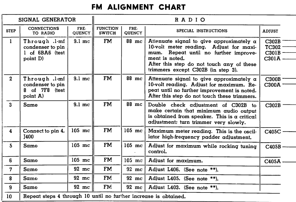
The procedure calls for using a powdered-iron tuning core (see the note toward the bottom of the FM alignment instructions) which I don't have. I think I've seen it called a magic wand. Can this be done without one? If so, what is the procedure?
Thanks for any help!
Rich
Posts: 641
Threads: 48
Joined: Mar 2017
City: Gap Mills Wv 24941
wow, our posts criss crossed paths... good job.
ok,,,
toss the instructions... at least thats what i had to do and it worked.
first ,, find out if your AM stations agree with you pointer
if no- mentally note this and compare how far you are off on FM.
check your AM alignment and target a live station thats near to or around 1500 to 1600 am. Get that part of the spectrum nailed down.
now double back and check to see if your satisfied with FM stations compared to your pointer.
if no- split the difference between the two
my zenith AM / FM beat me up like this for two or three days before i figured out a point i could live with.
remember one thing.. you generally have piss poor reception down in the lower AM and FM bands anyway... and you generally have poor reception in the really HI AM bands....
if you take the wack a mole approach and get the middle 80 to 90% accurate ,, the stuff on the ends probably never worked well even from the factory.
I think terry told me for AM,, tune to something near 1600AM and adjust things to make this range come in good and most of the stuff on either end for AM will be close ,, but we never get them dead on.
Posts: 641
Threads: 48
Joined: Mar 2017
City: Gap Mills Wv 24941
so what was the root cause here,, your new IF cans you got,, you installed one wrong or what?
good vid,,, nice and clear
now you need to do a modification and add an S-meter like i did using parts form a 9$ analog meter.. i posted it here
looks like the set is ready for another few decades of enjoyment
who knows though,, maybe new tech will make radio become obsolete,, like what happened to analog TV now
(This post was last modified: 02-10-2019, 02:45 PM by jcassity.)
Posts: 182
Threads: 5
Joined: Feb 2017
City: Cedar Rapids Iowa
Thanks for all your help Scott! I appreciate all the time you've put into posting suggestions for me ;) And everyone else that has helped me...there have been many. I don't think I'm done yet...my biggest concerns are the little bit of distortion and the fact that I receive 90.9 at about 107 on the dial. And I'm still concerned about the 15k 2W resistor dissipating close to 2 watts. I think it's better now that the IF can has been replaced and FM is working but I'll take another reading tomorrow. I'm also concerned that the output (at the voice coil) rides on top of a sine wave, about 200mV peak-to-peak. Is that normal?
Maybe I'm worrying too much, but I want this thing to work right for a long time.
Ok, to answer your question Scott...I'm pretty sure the 3rd IF (AM detector/FM discriminator) was the primary problem. I can't explain why I didn't get solid FM when I had it tacked into the circuit, but it did allow me to do the FM alignment properly, which I couldn't do before replacing it. Perhaps I had it tacked in improperly but I don't think so. But when I soldered it in permanently I did make a mistake, and once I corrected that it came to life and I'm glad. 
Rich
Posts: 641
Threads: 48
Joined: Mar 2017
City: Gap Mills Wv 24941
i would have to go back and look but your push pulls.. what is your voltage there,, i think you posted it somewhere......... i think i have about 300v,,.
also,,
a long while back you asked me to take a voltage reading on a resistor on either end............. i still owe you that
Users browsing this thread: 3 Guest(s)
|
|
Recent Posts
|
|
Zenith H725
|
| Here's what the inside of AM IFT2 looked like, and the other pic shows the discs I made to take place of the mica and ke...EdHolland — 07:40 PM |
|
Zenith H725
|
| IF2 will need replacement caps. The arcing was severe enough that the mica is pitted and holed where the HT flashed over...EdHolland — 04:04 PM |
|
My Philco 37-116 Restore
|
| Measuring from center tap like the tube voltages show. Cap 127 is isolated from ground. Cap 127 shown in upper left of p...dconant — 08:05 AM |
|
My Philco 37-116 Restore
|
| Are you measuring relative to the centertap or the GND?morzh — 11:57 PM |
|
Philco 610B oscillator wiring
|
| Still not clear on the wiring interface between the 6A7 and oscillator. After refering to the available schematics and s...Tubester — 07:18 PM |
|
Refinishing Ideas
|
| My 37-116 code 121 is the best sounding radio i have...a daily driver. Since we are talking about "changes". ...poulsbobill — 07:18 PM |
|
My Philco 37-116 Restore
|
| Hello, I finally got brave enough to take the cans off the Expander Unit. Got the grid cap wires replaced and back toget...dconant — 06:50 PM |
|
Zenith H725
|
| I got into the first AM IF can today, and found its mica was cracked. Amazing that it was still working. This one makes ...EdHolland — 06:10 PM |
|
Philco model #20
|
| AHH HA , I got it and can’t thank you fellows enough , when I changed the capacitors I took the advice and did not unsol...onlyrick — 02:24 PM |
|
Zenith H725
|
| Hello Ed,
yes, I like letting projects run for few days to make sure they don't start acting up .
Sincerely Richardradiorich — 01:03 PM |
|
Who's Online
|
| There are currently no members online. |

|
 
|


![[-] [-]](https://philcoradio.com/phorum/images/bootbb/collapse.png)


