Posts: 1,393
Threads: 46
Joined: Nov 2017
City: Menlo Park
State, Province, Country: CA
Good project Ron, I've enjoyed reading the progress so far - and look forward to the next installment. Marantz equipment is almost always worthy of saving, but projects that don't stay fixed are taxing.
A couple of years ago, I came by a Dynaco ST400. One channel was kaput, so I went about recapping the driver boards, replacing all the driver transistors, and the outputs. It worked like a charm until next morning, when I was greeted with "Kapow!" at switch-on. The cause was the collapse of the plastic bushings used to mount the driver transistors to the heat sink. That was the sound of a fairly inexpensive project getting more costly. Time to do replace all the drivers and outputs again... with new bushings. This fixed the issue, although I have yet to find a use for this nice amplifier.
I wish you well, and hope you are soon back at this project.
Cheers,
Ed
I don't hold with furniture that talks.
Posts: 13,776
Threads: 580
Joined: Sep 2005
City: Ferdinand
State, Province, Country: Indiana
Thanks Ed.
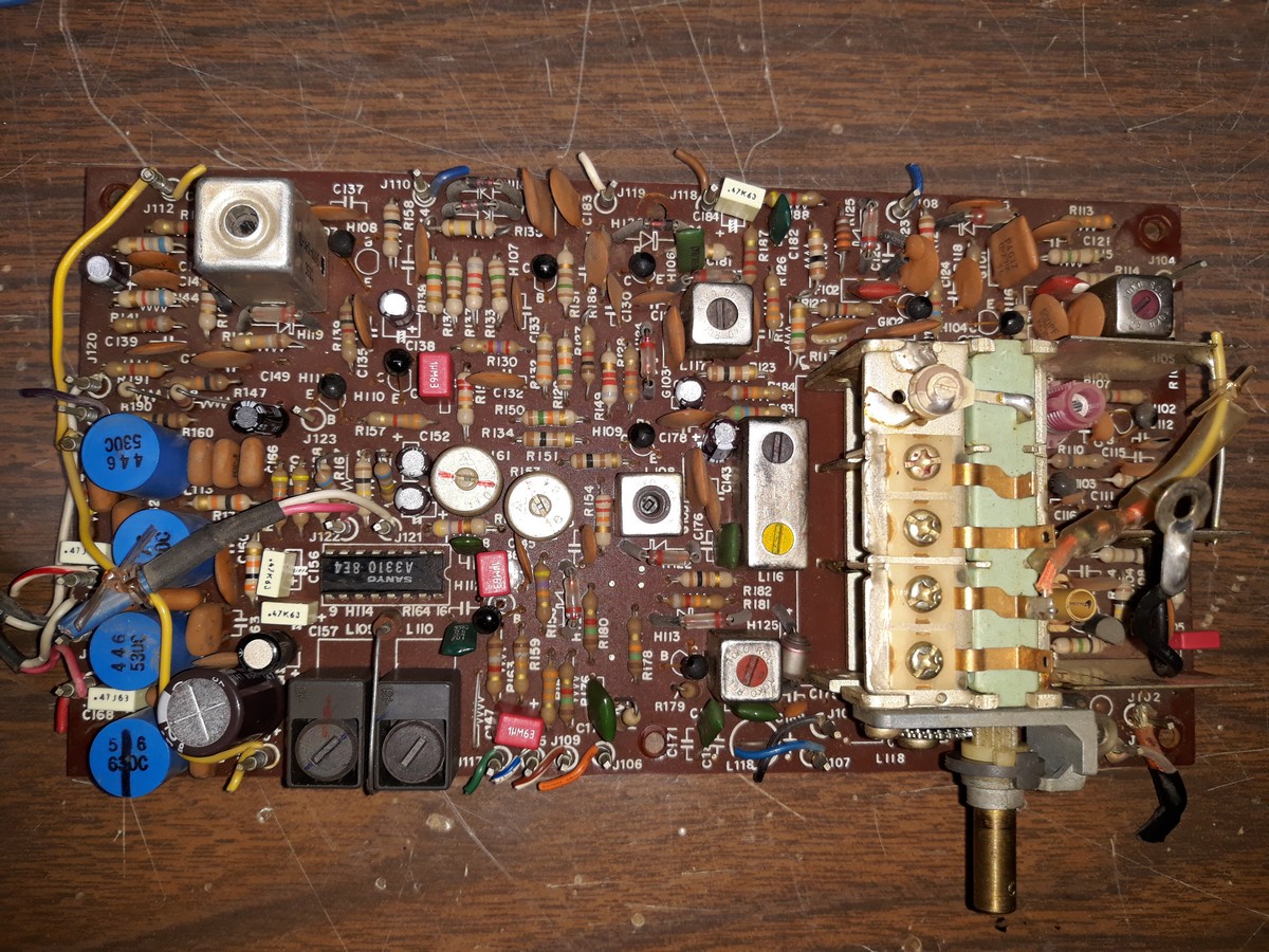
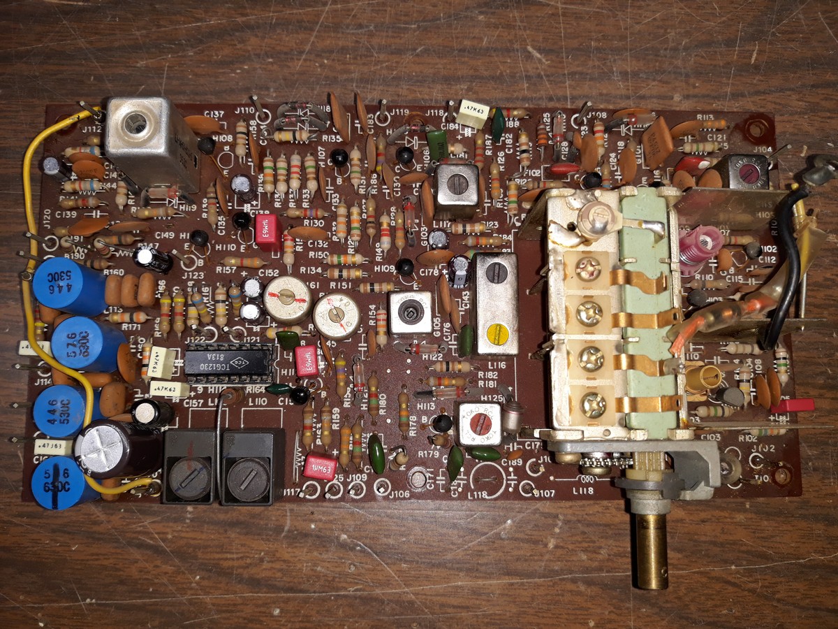
With one more day (tomorrow) before the next chemo session, I got busy this afternoon and finished replacing electrolytics in the replacement 4230 tuner board.
For electrolytics rated at 1 uF or lower, I replaced those with film. You can see those as red or ivory boxes mounted on the board.

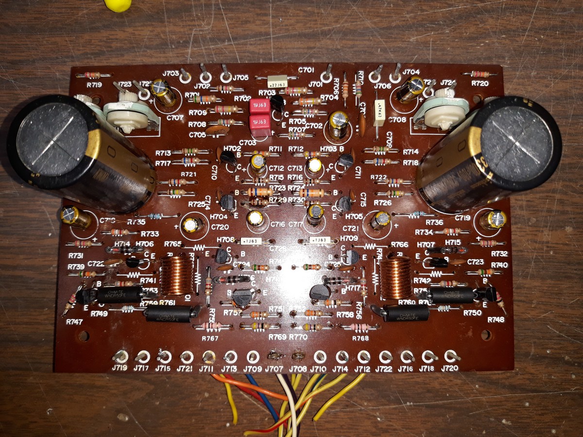
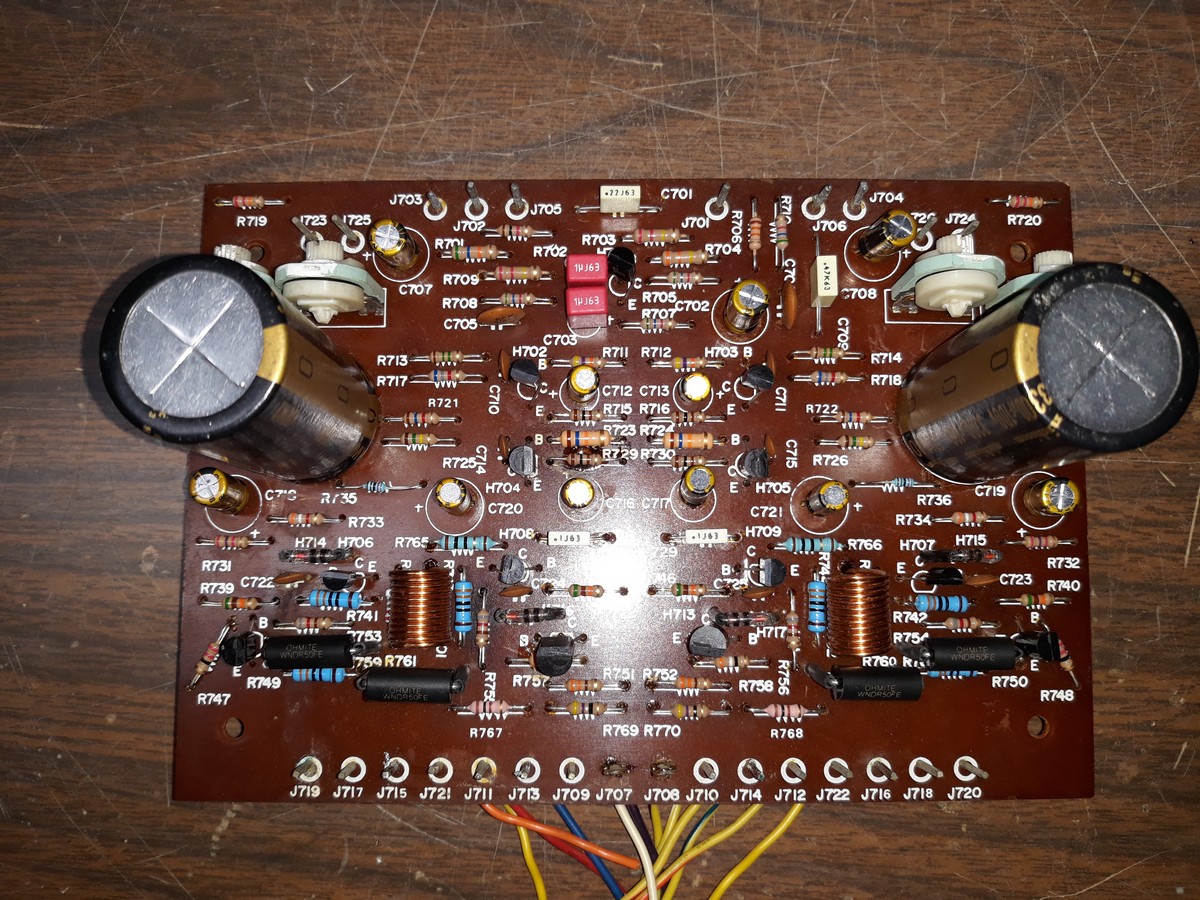
The replacement left channel audio output board is waiting for some 330 ohm resistors, but is otherwise finished.

I still need to replace the audio output transistors, which mount to a large heatsink which is then attached to the audio output board by way of four screws and several wires. I have the transistors.
Next time...in a week and a half or so. By then the resistors will be here.
--
Ron Ramirez
Ferdinand IN
Posts: 13,776
Threads: 580
Joined: Sep 2005
City: Ferdinand
State, Province, Country: Indiana
So...
Since my last post, I have received 330 ohm resistors, a couple NOS TCG (NTE) 1230 multiplex decoder ICs, and some 16 pin DIP IC sockets.
This evening, I finally felt good enough to get back to the Marantz boards.
In short order, I had removed the original LA3310 multiplex decoder IC and replaced it with a 16 pin DIP IC socket and a NOS TGC (NTE) 1230 IC.
I wanted to use the socket to make any future replacement of the IC nice and easy. I had read that this IC may have been the cause of loss of FM in the original tuner board, so I wanted to make sure the IC in this board was replaced. I did the same thing in a Lafayette solid state receiver I have. Adding a DIP IC socket did no harm to the receiver, it works fine and if replacement of the IC is ever needed, it will be a breeze (assuming the IC is still available in that future time).
The tuner board is now ready for installation in the 4230.

Then, I turned my attention to what will be the replacement left channel audio output board.
I stuffed it with 330 ohm resistors. I found that I had forgotten to install two 10 ohm resistors; these, too, were installed.
The board itself is now ready.

All that remains is to replace the audio output transistors and wire them into the left channel audio output board.
Then comes the fun of pulling the current left channel audio output assembly and replacing it with this one, removing and resoldering about a million wires in the process. Then lather, rinse and repeat for the tuner board.
Keeping fingers crossed...
P.S. I plan to rebuild the original tuner board in the same manner as I did this one, in case I ever need it. I have so much time and $$$ tied up in this Marantz that I would never get a fraction of it back, so it's a keeper.
--
Ron Ramirez
Ferdinand IN
Posts: 16,533
Threads: 573
Joined: Oct 2011
City: Jackson
State, Province, Country: NJ
Ron, in case you don't wear antistatic bracelet when handling the IC - do wear it.
People who do not drink, do not smoke, do not eat red meat will one day feel really stupid lying there and dying from nothing.
Posts: 13,776
Threads: 580
Joined: Sep 2005
City: Ferdinand
State, Province, Country: Indiana
100% correct and I knew that - but I forgot to do so last night! 
Oh well. I'll try it anyway. If it doesn't work it will be easy to replace now that it has a socket. I have one more IC that was intended for the original tuner board that I can use if necessary. Also, NTE 1230 ICs are still in production. Not real cheap at $10-11 each but still available.
--
Ron Ramirez
Ferdinand IN
Posts: 16,533
Threads: 573
Joined: Oct 2011
City: Jackson
State, Province, Country: NJ
Well, they have some resilience, so just touching them or even zapping a bit does not necessarily destroy them, which is good news, but some discharges are worse than others (human model is 150pF / 8kV) and this winter is pretty dry, I keep getting zapped at work. So in the winter I always put the bracelet on when doing stuff with boards.
People who do not drink, do not smoke, do not eat red meat will one day feel really stupid lying there and dying from nothing.
Posts: 13,776
Threads: 580
Joined: Sep 2005
City: Ferdinand
State, Province, Country: Indiana
Makes perfect sense. Although (knock on wood) I have yet to be zapped in the basement this winter. And I wear rubber/plastic-soled shoes (either tennis shoes or slippers) when in the basement. The concrete floor is too bloody cold to go barefoot or just in socks.
--
Ron Ramirez
Ferdinand IN
Posts: 16,533
Threads: 573
Joined: Oct 2011
City: Jackson
State, Province, Country: NJ
When I work in the basement, I run my addition's furnace (it has one register in the workshop room) full time (else it practically does not have to run as I keep the door in addition open and the temp there stays around 65F due to the main part of the house air getting in, except during bad cold spells when I know I have to run it or else something will freeze), and then on top of that I run space heater 3ft from where I stand.
And even with that I do not go there often. It is uncomfortable.
People who do not drink, do not smoke, do not eat red meat will one day feel really stupid lying there and dying from nothing.
Posts: 13,776
Threads: 580
Joined: Sep 2005
City: Ferdinand
State, Province, Country: Indiana
Since my workbench is in the basement, I don't have a choice but to go down there if I want to work on anything.
I run a space heater under the bench. It helps a lot. The house's recirculating water heat system has (only) one radiator in the basement, about 10-12 or so feet from the workbench.
Upstairs, the radiators are in place of wallboard, mostly on the outer walls of the rooms - one exception being the kitchen where the radiators are along an interior wall. The system keeps the upstairs warm unless the outside temperature falls - and stays - below 20 degrees for days at a time.
--
Ron Ramirez
Ferdinand IN
Posts: 462
Threads: 40
Joined: Jun 2010
City: Lehighton
State, Province, Country: PA
Perhaps a small fan blowing across that basement radiator would help circulate some heat. I had a friend who replaced the basement radiator with a large truck radiator and mounted a fan behind it controlled by a heat sensor. When the radiator warmed up the fan kicked on. It kept the whole basement comfortable.
Posts: 13,776
Threads: 580
Joined: Sep 2005
City: Ferdinand
State, Province, Country: Indiana
I like that idea, Larry. I don't know if I can implement a fan solution, though, the way it is made.
Now back to the Marantz...
I installed the recapped tuner board, burning and severing the dial cord in the process. 
I then hooked up a makeshift FM antenna and plugged in some headphones, and tried it out.
The result:
AM is dead. FM is working but only in mono. And in FM, the signal strength meter is not working (but the center channel meter is).
        
I think I'm ready to throw in the towel on this one.
[Video: https://youtu.be/_VrFV5r8cs0]
--
Ron Ramirez
Ferdinand IN
Posts: 496
Threads: 15
Joined: Mar 2013
City: Weymouth Ma
I have a Marantz 22 waiting in the cellar .One channel has low output and it appears to be the pre amp board but I am in no hurry to do the work. I recently did find a good article on line which will help me get thru it.
Henry
Posts: 3,160
Threads: 59
Joined: Apr 2011
City: Lexington, KY
(03-10-2019, 04:24 PM)Ron Ramirez Wrote: .........I think I'm ready to throw in the towel on this one.....
Sleep on it a few days or weeks Ron and maybe you'll get an idea or two.
Once Terry started taking in modern receivers he realized he was in over his head. Between parts availability, his unfamiliarity with the solid state circuits, and lack readily of available documentation left him with more than one stack of receivers. He still has over a dozen lined up in his basement that he'll never get to, but that's another story.
John KK4ZLF
Lexington, KY
"illegitimis non carborundum"
Posts: 13,776
Threads: 580
Joined: Sep 2005
City: Ferdinand
State, Province, Country: Indiana
Wise advice indeed, John, thanks. I am going to recap the original tuner board and try it out. The replacement tuner board seems to be in need of a serious realignment on FM. No idea why AM is dead on the replacement board.
--
Ron Ramirez
Ferdinand IN
Posts: 244
Threads: 11
Joined: Oct 2011
City: Black Mountain, NC
Ron,
Sometimes those old Phenolic pc boards can develop hidden leakage paths that will drive you mad.
Hope that's not the case.
Mike
Cossor 3468
GE 417A
Philco 118H
Radiola 17/100
Scott 800B6
Silvertone 6130
Stromberg 535M
Truetone D1952
Users browsing this thread: 1 Guest(s)
|
|
Recent Posts
|
|
1949 Motorola 5A9M
|
| This would be the second portable in the "other radios" forum where I have a similar one in my collection. I h...Arran — 12:41 AM |
|
Looking for any info: 1977 Ford-Philco Console Hi-Fi Turntable and Radio
|
| Hi PittsburgTost.
The record changer looks like a Garrard or BSR (Likely Garrard). The spindles just pull out and pu...MrFixr55 — 11:57 PM |
|
Looking for any info: 1977 Ford-Philco Console Hi-Fi Turntable and Radio
|
| Hello PittsburghToast ,
Welcome aboard and it looks like gary may have something for you !
now if I dig through my se...radiorich — 11:35 PM |
|
Model 80 Antenna Issue?
|
| You are kind of on the right path. You can touch the grid cap of the Detector/Oscillator 36 tube. I'm expecting a respon...RodB — 08:48 PM |
|
Looking for any info: 1977 Ford-Philco Console Hi-Fi Turntable and Radio
|
| Welcome to the Phorum, PittsburghToast! I found an old thread that my interest you regarding the quality and worth of P...GarySP — 08:48 PM |
|
Looking for any info: 1977 Ford-Philco Console Hi-Fi Turntable and Radio
|
| Welcome to the Phorum!
:wave:
We do not have anything on that unit in our digital library. There is a Sam's Photof...klondike98 — 08:47 PM |
|
Model 80 Antenna Issue?
|
|
I’ve replaced all the caps and resistors and the radio is working but minimal volume unless I put my hand near the re...Hamilton — 08:24 PM |
|
Looking for any info: 1977 Ford-Philco Console Hi-Fi Turntable and Radio
|
| Hi there! this is my first time posting. I recently picked up this Ford-Philco Console record player and radio at a yard...PittsburghToast — 07:28 PM |
|
philco predicta
|
| I found that where I have the 140v B+ there is 50v and the tuner receives 235v through the orange cablecgl18 — 04:14 PM |
|
Philco 91 code 221
|
| Chassis grounds thru rivets is another good place to look. Oh and the stator screws on the tuning cap where the leads at...Radioroslyn — 08:11 AM |
|
Who's Online
|
| There are currently no members online. |

|
 
|


![[-] [-]](https://philcoradio.com/phorum/images/bootbb/collapse.png)


