Maas-Rowe Carillon Amplifier
Posts: 16,577
Threads: 574
Joined: Oct 2011
City: Jackson
State, Province, Country: NJ
I think it is a cathode follower to the voltage created by the 620k/510k resistive divider of the plate voltage to be used as the SG voltage for 6550. Supposedly the follower will stabilize it better due to low output impedance compared to the divider itself.
People who do not drink, do not smoke, do not eat red meat will one day feel really stupid lying there and dying from nothing.
Posts: 1,199
Threads: 49
Joined: Oct 2017
City: Allendale, MI
So the benefit in actual operation would be what, better tube protection? Less distortion in overload condition? Less distortion overall?
(This post was last modified: 10-03-2019, 09:14 PM by rfeenstra.)
Posts: 16,577
Threads: 574
Joined: Oct 2011
City: Jackson
State, Province, Country: NJ
I doubt it. The SG voltage would be more stable, so possibly less unwanted modulation due to various effects from SG to the output.
People who do not drink, do not smoke, do not eat red meat will one day feel really stupid lying there and dying from nothing.
Posts: 1,199
Threads: 49
Joined: Oct 2017
City: Allendale, MI
I remember Dave Gillespie on the AK forum talking about an active SG supply for Fisher amps allowing full output with the idle current being quite a bit lower than normal. Perhaps this circuit does something similar.
Posts: 4
Threads: 0
Joined: Oct 2019
City: GLENDALE
State, Province, Country: CA
Why not use 1n4007 diodes and a dropping resistor. You will eliminate the filament current on each tube replaced. I have done this to some old Dynaco tube amps. I copied my Marantz 8B, it uses silicon diodes. Marantz knew the advantages.
Posts: 1,199
Threads: 49
Joined: Oct 2017
City: Allendale, MI
I've done that as well on a couple of tube amps in old organs.
Posts: 1,199
Threads: 49
Joined: Oct 2017
City: Allendale, MI
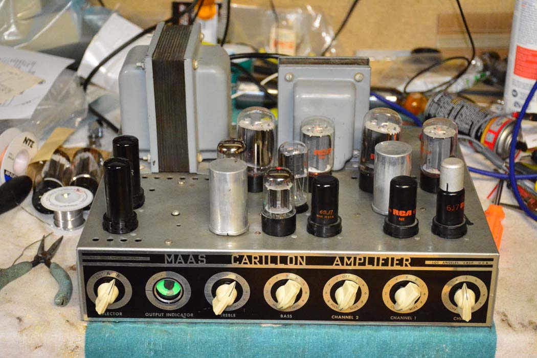
I've rebuilt the amp replacing all electrolytics and tubular caps. I found a couple of 5Z4's in my stash that I didn't know I had, then proceeded to track down a bunch of intermittent issues. Most of the grounding tabs are on the tube sockets that are riveted to the chassis. The top of the chassis was painted before the tube sockets were riveted in. I had a lot of loose rivets! I wound up soldering all of the tube sockets to the chassis to eliminate the problem. Except for a couple of microphonic tubes , it seems to work good.
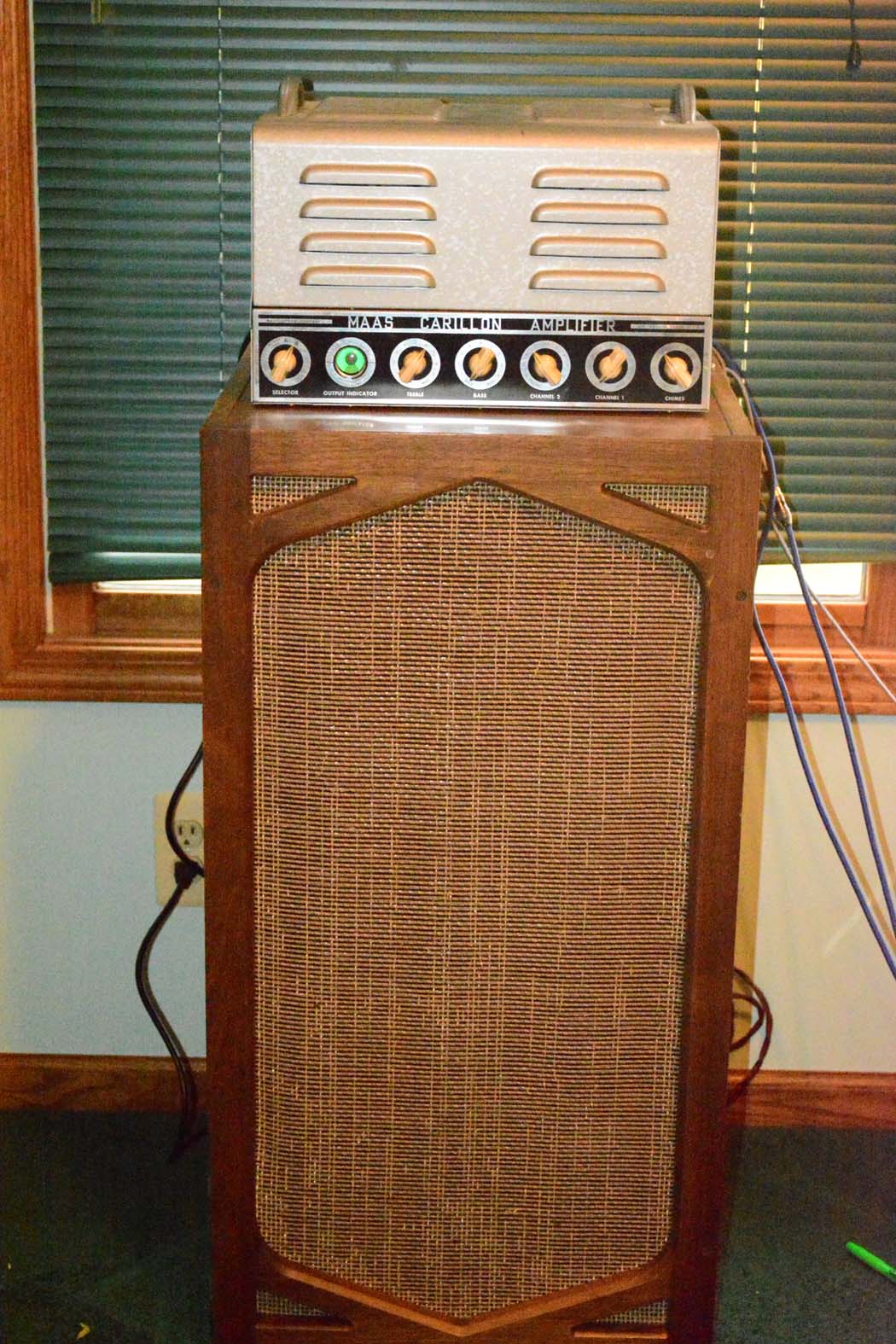
The amp has found its home on the top of an old Allen organ speaker in my 13 year old grandson's bedroom. He's learning to play bass guitar and the amp and speaker work quite nicely for that (of course, none of the effects). He's really geeked to have a tube amp for his bass and the 15" driver in the speaker really shakes the room! He's going to have to keep the volume down.


(This post was last modified: 11-03-2019, 12:09 AM by rfeenstra.)
Posts: 3,156
Threads: 56
Joined: Apr 2011
City: Lexington, KY
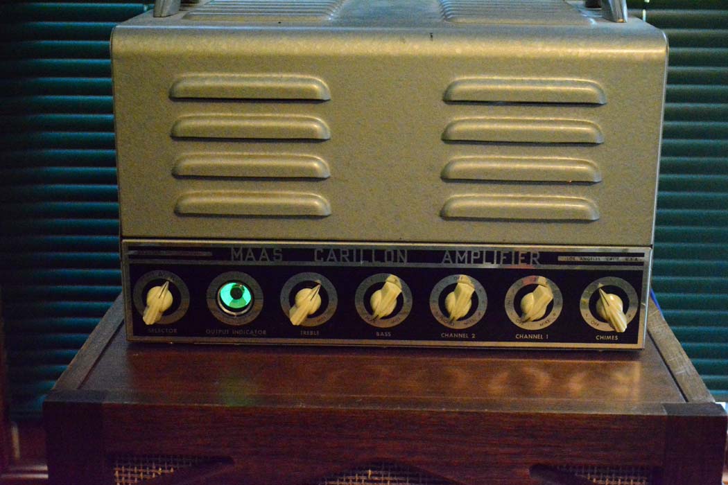
The amp came out looking beautiful and looks great sitting on the Allen speaker. Your grandson will have a ball learning to play bass through that amp & speaker.
John KK4ZLF
Lexington, KY
"illegitimis non carborundum"
Posts: 1,401
Threads: 46
Joined: Nov 2017
City: Menlo Park
State, Province, Country: CA
Nice amp, and I bet that is a fun bass rig. My son and I have been learning. The little 10" solid state practice amp is OK, but this makes me think something else is needed....
I don't hold with furniture that talks.
Posts: 1,199
Threads: 49
Joined: Oct 2017
City: Allendale, MI
My grandson loves it! At 50 watts output and an efficient speaker, it shakes things up.
Posts: 325
Threads: 34
Joined: Dec 2019
City: Elkhart
State, Province, Country: Indiana
I was given Newcomb's bigger version of this Amplifier which was a Newcomb "Pathfinder" Model E-75 Amplifier that was good for 75 Watts.
The tube line-up of that amplifier was 2 7027-A (KT-88), a 6V6, a 6C4, and 2 12AX7As (All RCA Branded Tubes), and according to the service manual for the Newcomb "Pathfinder" Model E-75 Amplifier, the 6V6 tube in this circuit (and yours as well) was used as a regulator tube (as opposed to using an old school 01A Gas Regulator Tube), so yes in your amplifier the 6V6 tube is a regulator tube.
Hope this helps.
Posts: 1,199
Threads: 49
Joined: Oct 2017
City: Allendale, MI
Thank you! that's what I suspected.
Posts: 5
Threads: 0
Joined: Jun 2020
City: Strongsville
State, Province, Country: OH
Do you have a full version of these schematics you'd be willing to share?
I have a 4*6l6 500 and am curious if my transformer specs match up with the schematic. I'm also curious what this large inductor is inside the amp. I don't even see it on your schematic and I can't get a reading on it.
Posts: 1,199
Threads: 49
Joined: Oct 2017
City: Allendale, MI
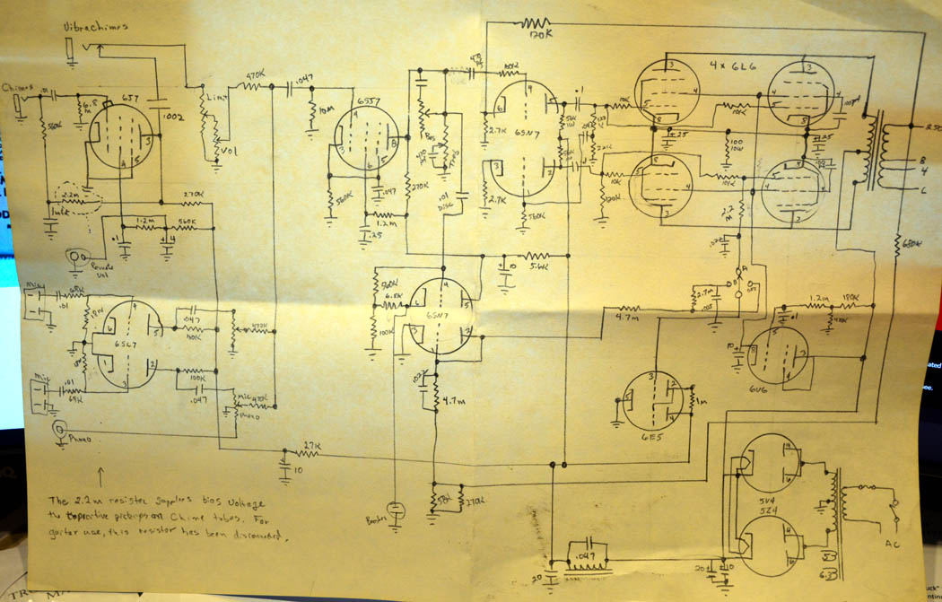
I do not have the factory schematic for this amp, just a similar one. Perhaps captainclock1988 has a complete schematic for the Newcomb E-75. My amp has an inductor under the chassis that is part of the HV filtering for the pre amp/driver section of the amp. The only schematic I have is one I hand drew. I have no specs on the choke. Here is a photo of my hand drawn schematic. The choke is found on the lower edge near the 5Z4's.

Posts: 7,305
Threads: 270
Joined: Dec 2009
City: Roslyn Pa
If you do some rough calculations your looking at 45 ma and the inductance that = 120cy with a .05 mfd cap in parallel with it.
GL
When my pals were reading comic books
I was down in the basement in my dad's
workshop. Perusing his Sam's Photofoacts
Vol 1-50 admiring the old set and trying to
figure out what all those squiggly meant.
Circa 1966
Now I think I've got!
Terry
Users browsing this thread: 1 Guest(s)
|
|
Recent Posts
|
|
Philco 42-345 Restoration/Repair
|
| Ok MrFixr55,
I have tried the DeoxIT D5 on the band switch and even though it has relieved the tension I felt when turn...osanders0311 — 11:11 AM |
|
Part numbers to model cross
|
| Is there a reference somewhere where you can punch in Philco part numbers and see what models those parts were used in?Jim Dutridge — 10:17 AM |
|
Philco 42-345 Restoration/Repair
|
| Hi OSanders,
Look carefully at the band switch. Turn it slowly and "wiggle" it around the desired band. ...MrFixr55 — 12:33 AM |
|
5U4 vs 5Z4 tubes
|
| I think that RCA and GE introduced metal tubes in the USA in 1936. I don't know if they were being made by RCA, GE or b...MrFixr55 — 11:20 PM |
|
Philco 42-345 Restoration/Repair
|
| Vlad95,
Thank you for the stringing guides and wow there are so manyosanders0311 — 06:01 PM |
|
5U4 vs 5Z4 tubes
|
| A pre war Hallicrafters, and an early one too, very nice! 1936 is pretty early for metal tubes too, which would explain ...Arran — 05:58 PM |
|
Philco 42-345 Restoration/Repair
|
| Thanks Rod,
"When you hear the background hiss and no station it usually indicates that the oscillator quit" ...osanders0311 — 05:52 PM |
|
Philco 42-345 Restoration/Repair
|
| RodB
:beerchug:Vlad95 — 10:22 AM |
|
Philco 42-345 Restoration/Repair
|
| Vlad, you nailed it. Swiss and German roots.RodB — 09:54 AM |
|
5U4 vs 5Z4 tubes
|
| Well this is a Hallicrafters SX/9 circa 1936.
No real issues so far although I dodged a real bullet with a cap that was...bridkarl — 07:59 AM |
|
Who's Online
|
There are currently 1455 online users. [Complete List]
» 1 Member(s) | 1454 Guest(s)
|
|
|

|
 
|


![[-] [-]](https://philcoradio.com/phorum/images/bootbb/collapse.png)


