model 38-10 no reception after recap
Posts: 21
Threads: 5
Joined: Oct 2019
City: Boston
State, Province, Country: MA
Hi all,
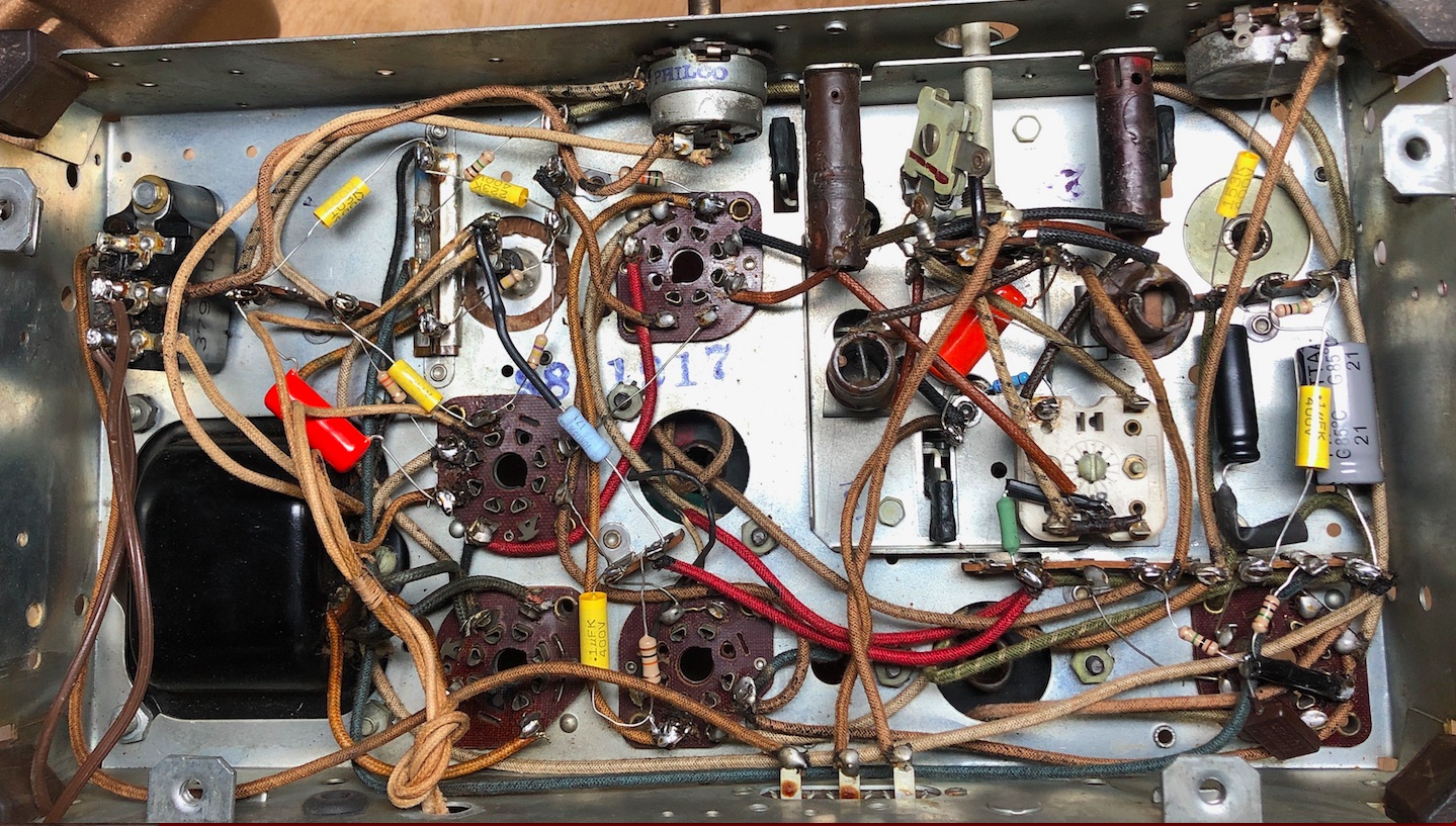
I've completed my first overhaul, replaced all capacitors including cans and bakelite block, (except mica), all resistors, new rectifier socket and tube. (this pic taken before I replaced the socket)
The good news is that it did not explode or burn out after powering up. All tubes lit, but I do not have a way to check if they are all good. Bad news is that I get no reception on AM or shortwave. I get a little air through speaker, nothing much else. 10' of 22G wire attached to red antenna terminal. Nothing attached to black.
What are the next steps to sorting this out? Thanks for any help you can lend this beginner.

Posts: 7,295
Threads: 268
Joined: Dec 2009
City: Roslyn Pa
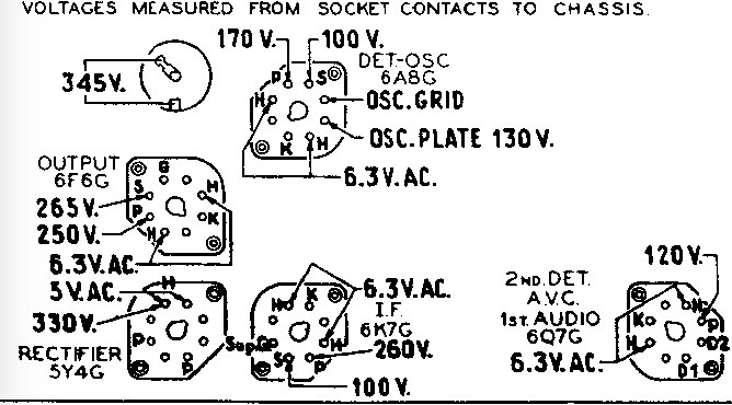
Probably the easiest thing to do would be is to do some voltage checks to see if you got voltage where it needs to be. Go over the the 6F6 tube and measure the DC voltage from the chassis to pin 3 of the tube and then measure pin 4. Both pins should have abt 250v or so on them.
When my pals were reading comic books
I was down in the basement in my dad's
workshop. Perusing his Sam's Photofoacts
Vol 1-50 admiring the old set and trying to
figure out what all those squiggly meant.
Circa 1966
Now I think I've got!
Terry
Posts: 16,476
Threads: 573
Joined: Oct 2011
City: Jackson
State, Province, Country: NJ
Touch the grid cap of 2nd detector 6q7.
See if you have hum in the speaker.
People who do not drink, do not smoke, do not eat red meat will one day feel really stupid lying there and dying from nothing.
Posts: 21
Threads: 5
Joined: Oct 2019
City: Boston
State, Province, Country: MA
Thanks. Pin 3 is settling in at around 283v, pin 4 278v. When I touch a probe to the top of 6Q7 the speaker buzzes. The grid cap is loose (connected to wire, but wobbles) on 6A8.
Posts: 7,295
Threads: 268
Joined: Dec 2009
City: Roslyn Pa
Ok so that seems to be in good order. Have a look @ pins 3 and 4 on the 6K7 Should see some hv there too. On the 6A8 pins 3,4, and 6 will have some hv too but will be less on 4 and 6 vs pin 3.
If all that seem reasonable it's time to breakout the signal generator.
You may want to resolder the gridcap oin the 6A8 to be sure it's making a good connection.
When my pals were reading comic books
I was down in the basement in my dad's
workshop. Perusing his Sam's Photofoacts
Vol 1-50 admiring the old set and trying to
figure out what all those squiggly meant.
Circa 1966
Now I think I've got!
Terry
Posts: 21
Threads: 5
Joined: Oct 2019
City: Boston
State, Province, Country: MA
tube 6A8: pin3: 179v pin 4: 68v
tube 6K7: pin 3: 272v pin 4: 67v
tube 6Q7: pin 3: 232v (this one is double what the schematic lists)
tube 6F6: pin 3: 283v pin 4: 266v
tube 6A8: pin 3: 173v pin 4: 67v

Posts: 7,295
Threads: 268
Joined: Dec 2009
City: Roslyn Pa
Pin 6 of the 6A8?
Also have a look@ pin 5 should see a little bit of - voltage there with a modern meter.
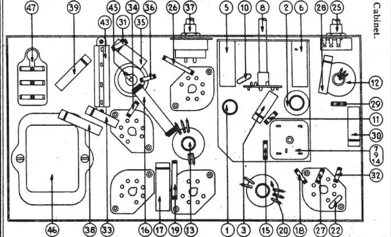
And are #19 and 26 within tolerance?
When my pals were reading comic books
I was down in the basement in my dad's
workshop. Perusing his Sam's Photofoacts
Vol 1-50 admiring the old set and trying to
figure out what all those squiggly meant.
Circa 1966
Now I think I've got!
Terry
(This post was last modified: 02-22-2020, 09:58 PM by Radioroslyn.)
Posts: 21
Threads: 5
Joined: Oct 2019
City: Boston
State, Province, Country: MA
Posts: 7,295
Threads: 268
Joined: Dec 2009
City: Roslyn Pa
Tada! we got it. It seems that either #15 is open or #5 between pins 4 and 3 are open. Which ever you need the 130v or so on the plate pin of the oscillator section of the pentagrid mixer and it's getting lost down by #15.
With the set off measure the resistance across pins 3 and 4 of #5 (oscillator coil). Should see a low resistance like an ohm or so. If not remove the coil and give it a close inspection for rot (green spots) or a break in the wire.
When my pals were reading comic books
I was down in the basement in my dad's
workshop. Perusing his Sam's Photofoacts
Vol 1-50 admiring the old set and trying to
figure out what all those squiggly meant.
Circa 1966
Now I think I've got!
Terry
(This post was last modified: 02-22-2020, 10:53 PM by Radioroslyn.)
Posts: 21
Threads: 5
Joined: Oct 2019
City: Boston
State, Province, Country: MA
Thanks, Terry. Are you referring to #15 resistor and #5 Osc. Transformer? What am I looking for... bad connections to/from either? bad component? Not sure how to rectify this.

Posts: 7,295
Threads: 268
Joined: Dec 2009
City: Roslyn Pa
>Are you referring to #15 resistor and #5 Osc. Transformer?
Correct!
You can follow the hv from the bottom end of #15 (5000 ohm resistor) to the top end of 15 then to terminal 4 of the oscillator coil then to terminal 3 of the oscillator coil/pin 6 of the 6A8.
When my pals were reading comic books
I was down in the basement in my dad's
workshop. Perusing his Sam's Photofoacts
Vol 1-50 admiring the old set and trying to
figure out what all those squiggly meant.
Circa 1966
Now I think I've got!
Terry
Posts: 7,295
Threads: 268
Joined: Dec 2009
City: Roslyn Pa
It would seem that your wire is open from the coil to the tube socket or a bad solder joint where the wire is solder @ the socket. If that is ok pull the 6A8 out and measure pin 6's resistance to the chassis w/the set off. Should see a high resistance like 20 or 30K this eliminates a shorted socket. Measure the voltage @ pin6 w/o the tube in place maybe your tube is shorted.
When my pals were reading comic books
I was down in the basement in my dad's
workshop. Perusing his Sam's Photofoacts
Vol 1-50 admiring the old set and trying to
figure out what all those squiggly meant.
Circa 1966
Now I think I've got!
Terry
Posts: 21
Threads: 5
Joined: Oct 2019
City: Boston
State, Province, Country: MA
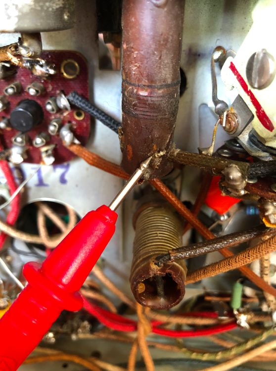
Got it! Seems Bad connections at these pins are the culprit. I was able to get 160v to the tube when I moved these a bit, making a connection. Can these be secured/soldered?
I have reception!! not many channels, but a few strong ones on AM and a few weak ones on SW.
This is great, thanks so much, Terry!
Now on to see how I improve reception (and make these connections more stable). Any thoughts welcome!!

Posts: 7,295
Threads: 268
Joined: Dec 2009
City: Roslyn Pa
Not sure which connections we are talking about but the coil you can gently scrape the wires at the solder connection and re solder. If it's the tube socket you can use a pair of needle nose pliers and gently pinch the connector on the socket w/o the tube in place. Be careful the metal can be weak and fold easily then your looking at a new socket.
To improve the performance you'll need a signal generator to adjust the IF amplifier and other stages of your set. Something simple is fine just need to verify it's accuracy.
When my pals were reading comic books
I was down in the basement in my dad's
workshop. Perusing his Sam's Photofoacts
Vol 1-50 admiring the old set and trying to
figure out what all those squiggly meant.
Circa 1966
Now I think I've got!
Terry
Users browsing this thread: 1 Guest(s)
|
|
Recent Posts
|
|
Need to purchase some accessories for restoration of my Old Philco Radio
|
| Here is a list of resources found in our online library that you might find useful. Mike's Gobs of Knobs email addres...klondike98 — 01:46 PM |
|
First Radio restoration
|
| Hi Tubeman,
Welcome to the Philco Phorum. Phamily Phriendly Pfun with Phine Pholks Phull of Philco Phacts. (See a p...MrFixr55 — 12:33 PM |
|
First Radio restoration
|
| You could post in the WANTED ADs section here on the Phorum and see if anyone has an RF generator that they want to sell...klondike98 — 11:55 AM |
|
Zenith H725
|
| Good ideas, thank you Arrange and Rich. I have the adhesive aluminum foil already and can try that immediately.
More ...EdHolland — 10:18 AM |
|
Graphics for majestic 1050 dial glass.
|
| Murf;
I found this thread on the ARF, the first photo has a pretty good view of the dial glass.
Regards
ArranArran — 01:12 AM |
|
Zenith H725
|
| hello Ed,
how about that speacial tape used for ducting it's like foil or how about thin piece of
aluminum roof flash...radiorich — 12:19 AM |
|
Zenith H725
|
| Ed;
One material that I have seen, but never tried for this was material for making exhaust gaskets, it's similar to ...Arran — 11:42 PM |
|
Zenith H725
|
| I just remembered, I have some hi temp silicone rubber material which could do the trick. Or a piece of FR4 laminate. Th...EdHolland — 08:39 PM |
|
Zenith H725
|
| The PSU filter cap arrived today (thank you USPS!) so I will work on that later.
Meanwhile, I have the dial, speaker...EdHolland — 06:42 PM |
|
Philco 610B oscillator wiring
|
| Thanks Terry. After checking my notes I think I recorded about -10v at the 6A7 G4/control grid. The screen grid (G3 &...Tubester — 05:59 PM |
|
Who's Online
|
| There are currently no members online. |

|
 
|


![[-] [-]](https://philcoradio.com/phorum/images/bootbb/collapse.png)


