Replacement output transformer for Zenith 5S29
Posts: 322
Threads: 60
Joined: Mar 2007
City: Toledo
State, Province, Country: OH
I recently got a Zenith 5S29 from a fellow collector and there is a static noise in the audio. Come to find out the output transformer is arcing. I can see a pretty blue arc at times. This radio uses a single 6F6 and the tube data says the load resistance for it connected as a triode should be 4000 ohms. Does this mean I need a transformer that measures 4000 ohms on the primary?
Posts: 1,824
Threads: 114
Joined: Jul 2014
City: Sneedville, TN
No, that would be the REFLECTED impedance of the speaker voice coil back through the transformer, and is a result of the ratio of primary to secondary windings of the transformer. First, you will need to know the resistance of the voice coil, then the ratio of that to 4000 ohms will give you that ratio. Something like this should do the job. https://www.tubesandmore.com/products/tr...output-8-w
Posts: 322
Threads: 60
Joined: Mar 2007
City: Toledo
State, Province, Country: OH
Its a 4 ohm speaker. I have several single ended output transformers on hand and I'm looking for a resistance reading that might be close to what I have that I can put in its place. The original is reading about 1500 but with it arcing I can't be sure of that value.
Posts: 7,303
Threads: 269
Joined: Dec 2009
City: Roslyn Pa
Jim,
The tube data chart is giving the data for several different configuration connections for the 6F6. Look at the schematic if it is triode connected before assuming that it is.
When my pals were reading comic books
I was down in the basement in my dad's
workshop. Perusing his Sam's Photofoacts
Vol 1-50 admiring the old set and trying to
figure out what all those squiggly meant.
Circa 1966
Now I think I've got!
Terry
Posts: 714
Threads: 9
Joined: Apr 2018
City: S. Dartmouth
State, Province, Country: MA
Pliny the younger
“nihil novum nihil varium nihil quod non semel spectasse sufficiat”
Posts: 322
Threads: 60
Joined: Mar 2007
City: Toledo
State, Province, Country: OH
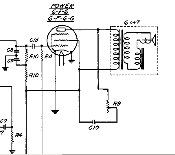
Chas, thanks for that link. Think I found one that will work but I am not really up on my amplifier configurations. It looks to me like the 6F6 is connected as a triode but as to what amplifier configuration I'm not sure.
http://www.nostalgiaair.org/pagesbymodel...024892.pdf
Posts: 714
Threads: 9
Joined: Apr 2018
City: S. Dartmouth
State, Province, Country: MA
No, Jim, the 6F6 is not connected as a triode...
Chas
Pliny the younger
“nihil novum nihil varium nihil quod non semel spectasse sufficiat”
Posts: 322
Threads: 60
Joined: Mar 2007
City: Toledo
State, Province, Country: OH
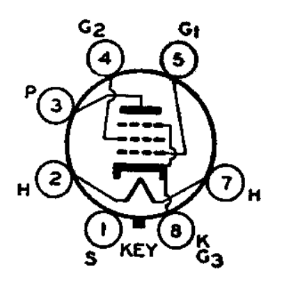
So if having the suppressor grid and cathode tied together does not constitute a triode connection what does and what sort of configuration is this 6F6 connected as?
Posts: 7,303
Threads: 269
Joined: Dec 2009
City: Roslyn Pa
Yes that's correct! The plate and screen grid are connected together in the triode configuration. So the plate impedance is going to be 7000 ohms instead of 4000 ohms. It very common in pentode tubes to have the suppressor grid and cathode connected together internally. The pentodes that have the sp grid separate from the cathode internally the sp grid can be used as an second input but the thing is that by the time the electrons get to the sp grid it doesn't have much control over the electron flow.
When my pals were reading comic books
I was down in the basement in my dad's
workshop. Perusing his Sam's Photofoacts
Vol 1-50 admiring the old set and trying to
figure out what all those squiggly meant.
Circa 1966
Now I think I've got!
Terry
(This post was last modified: 03-22-2020, 05:23 PM by Radioroslyn.)
Posts: 322
Threads: 60
Joined: Mar 2007
City: Toledo
State, Province, Country: OH
thanks Terry. I do have a transformer that if I input 42VAC i get 1VAC out, making it a 42:1 ratio. If I do the math correctly I get an impedance of just over 7000 ohms. Looks like I have a winner.
Posts: 322
Threads: 60
Joined: Mar 2007
City: Toledo
State, Province, Country: OH
I installed the replacement and no longer have the arcing issue but now at a high volume the audio starts motorboating. Even though the math says the impedance of the replacement is just over 7000 ohms could this be a result of an incorrect transformer?
Posts: 714
Threads: 9
Joined: Apr 2018
City: S. Dartmouth
State, Province, Country: MA
 03-27-2020, 11:20 AM
See:

Note this is the output of the schematic provided, there does not appear to be a triode connection.

For triode connection characteristics choose from one of the many offered, at least two offer some parameters to work with:
https://frank.pocnet.net/sheets64.html
Look for motorboating problems at the volume control, input to the amp incorrect wire position, bad ground rivets incorrect values of bias components. Bad or wrong volume control... Be sure shields are in place and properly grounded...
There may be a problem with high voltage on the tone control, if not now, in the future. What I often do with this circuit is to double the value of the "tone" cap. For example if it is 0.1mf make it 0.2mf and place one of these caps on each side of the tone control thus taking the high voltage off the control with the net result in capacitance being the same.
Another consideration is that QRM will cause cut-off of the output then the magnetic field collapses creating a very high voltage in the output transformer. The transformer can flash over at the wiring or internal and burn out. If the tone cap(s) have a dv/dt rating they will effectively absorb the destructive pulse. But if the cap is a plain yellow metallized without a Dv/Dt rating the metallizing will become shattered and the cap loose capacity. Successive QRN hits will cause the transformer to fail. Raising the voltage rating of this cap will not work, it is the internal design, can't deal with the pulse. BTW a vibrator buffer cap is good here...
GL
Chas
Pliny the younger
“nihil novum nihil varium nihil quod non semel spectasse sufficiat”
(This post was last modified: 03-27-2020, 11:35 AM by Chas.
Edit Reason: add more data...
)
Users browsing this thread:
|
|
Recent Posts
|
|
Model 80 Antenna Issue?
|
| Thanks Gary and Rod.
I also found an article in the Philco Repair Bench under Service Hints and Tips, about installi...Hamilton — 12:32 PM |
|
Model 80 Antenna Issue?
|
| Hello Hamilton, here is a little information found in our Philco Radio Library at the bottom of the Home page. Hope it ...GarySP — 11:28 AM |
|
Model 80 Antenna Issue?
|
| I did as you suggested and touching the middle of the volume control did nothing so the coil has to be rewound. Any idea...Hamilton — 10:19 AM |
|
1949 Motorola 5A9M
|
| This would be the second portable in the "other radios" forum where I have a similar one in my collection. I h...Arran — 12:41 AM |
|
Looking for any info: 1977 Ford-Philco Console Hi-Fi Turntable and Radio
|
| Hi PittsburgTost.
The record changer looks like a Garrard or BSR (Likely Garrard). The spindles just pull out and pu...MrFixr55 — 11:57 PM |
|
Looking for any info: 1977 Ford-Philco Console Hi-Fi Turntable and Radio
|
| Hello PittsburghToast ,
Welcome aboard and it looks like gary may have something for you !
now if I dig through my se...radiorich — 11:35 PM |
|
Model 80 Antenna Issue?
|
| You are kind of on the right path. You can touch the grid cap of the Detector/Oscillator 36 tube. I'm expecting a respon...RodB — 08:48 PM |
|
Looking for any info: 1977 Ford-Philco Console Hi-Fi Turntable and Radio
|
| Welcome to the Phorum, PittsburghToast! I found an old thread that my interest you regarding the quality and worth of P...GarySP — 08:48 PM |
|
Looking for any info: 1977 Ford-Philco Console Hi-Fi Turntable and Radio
|
| Welcome to the Phorum!
:wave:
We do not have anything on that unit in our digital library. There is a Sam's Photof...klondike98 — 08:47 PM |
|
Model 80 Antenna Issue?
|
|
I’ve replaced all the caps and resistors and the radio is working but minimal volume unless I put my hand near the re...Hamilton — 08:24 PM |
|
Who's Online
|
There are currently 1349 online users. [Complete List]
» 1 Member(s) | 1348 Guest(s)
|
|
|

|
 
|


![[-] [-]](https://philcoradio.com/phorum/images/bootbb/collapse.png)


