05-29-2020, 08:04 AM
I am working on a Philco 39-7. It is my third restore and first Philco. I have verified the radio works and removed the chassis. All voltages check out close to schematic. My initial measurement and tests indicate the following items are need attention.
1. Largest issue is crumbling rubber coated wires needs to be replaced. (picture attached)
2. The power supply transformer wires are all rubber coated and crumbling very badly. They will need to be replaced.
3. Volume/On/Off control is very scratchy and also the volume increases and decreases at random and when touched or moved.
4. Part #26 12 uf ecap was replaced under chassis with a 40 uf ecap.
5. All transformers ohm out close to value on schematic.
6. Part #29 .006uF cap to be replaced with .01uf 250v Y2 cap.
7. Needs new polarized AC line cord.
8. Needs AC line fuse installed inside chassis.
9. Dial lamp needs to be replaced.
10. Replace all eCaps (2) and wax/paper caps (5).
11. Replace out of spec resistors (5).
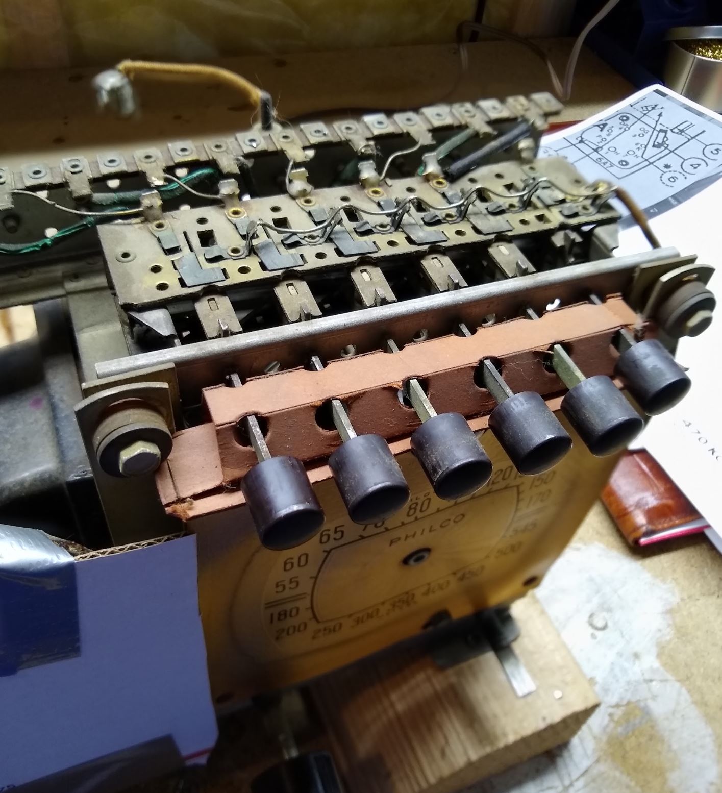
12. Button switching assembly seized and rubber wires crumbling. (picture attached)
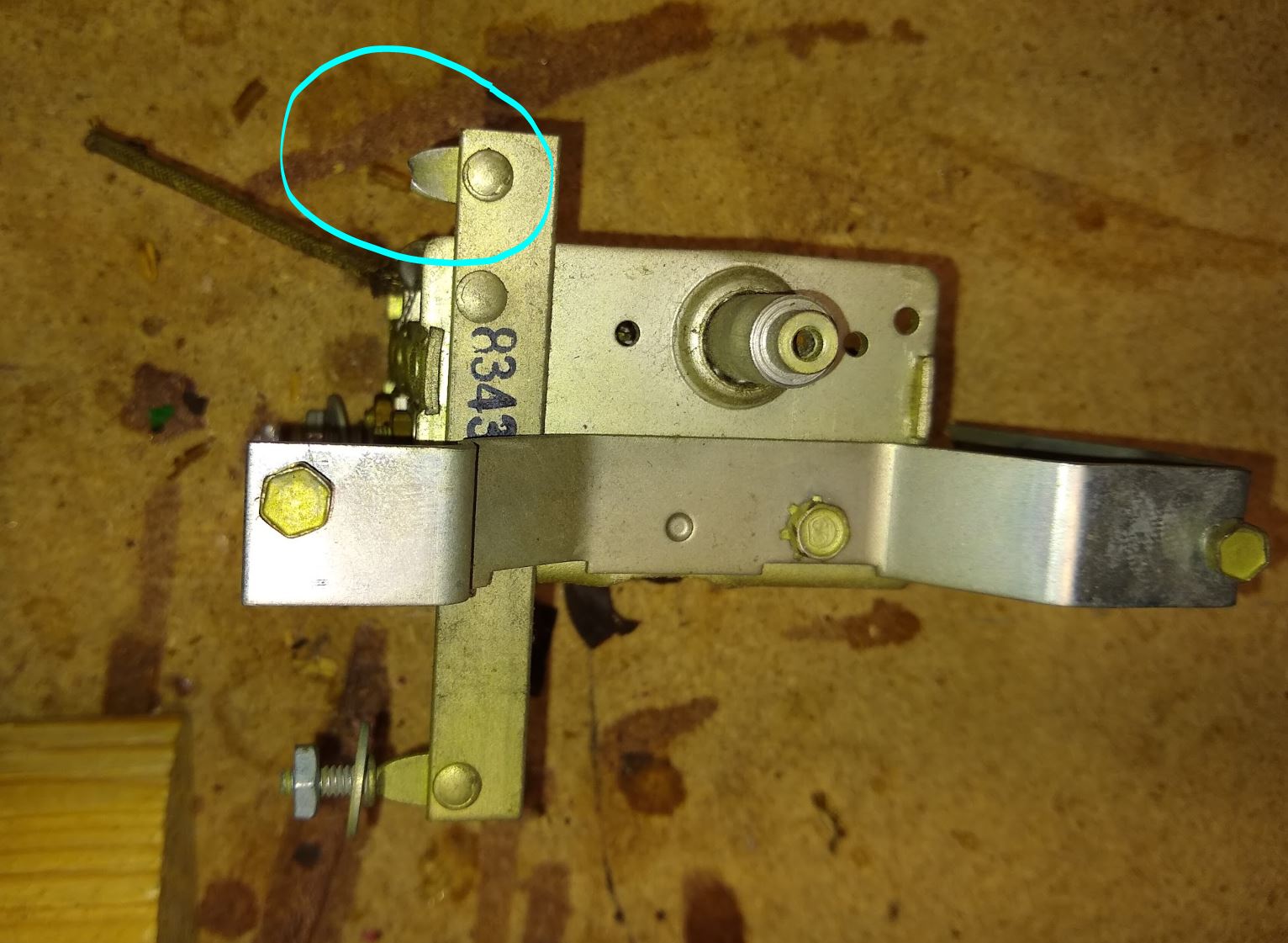
13. Tuning cap tower corrosion, crumbling rubber wires and broken mounting bolt. (picture attached)
14. Bending of dial face and rubbing of dial indicator.
15. Dial control restring needed.
16. Chassis and parts cleaning.
17. Cabinet refinishing.
At this early stage I a stripping down the chassis so that I can clean it and also work on some of the components parts. I could use some option, comment or advise on dealing with the following items.
#1 What is a suitable wire replacement for this radio? Gauge, stranded or solid conductor?
#2 What is the best way to replace the power transformer wires? The rubber coating is cracked and crumbling all the way to the case and I suspect also inside the case. I will know once I have removed it from the chassis. I have never replaced wires on a transformer before.
#3 Can the Volume/Off/On control be opened and repaired or does a replacement need to be sourced? Where can a replacement be found?
#4 Might there be a good reason that someone in the past replaced the 12uf ecap with on of such higher value (40uf)? Maybe a factory suggestion or just what he had at the time.
#12 Is there a recommended reconditioning process for these button switch assemblies? Is the point on the top of the IF can to secure the assembly grounded or insulated from the IF can? Mine had parts of what looks like a rubber washer but i cannot tell if it was for vibration or insulation.
#13 I broke one of the tuning tower mounting studs when removing the nut on the underside of the chassis. Picture attached. What are some ideas of how to repair this effectively?
#14 Is there a recommended method to flatten and secure the dial face graphics to the plate they are attached too so that there is enough clearance for the dial pointer to mover in a complete arc without touching it?
Regards, John


![[-] [-]](https://philcoradio.com/phorum/images/bootbb/collapse.png)


