Posts: 325
Threads: 34
Joined: Dec 2019
City: Elkhart
State, Province, Country: Indiana
@Radioroslyn:
Well the problem is that the radio used electrolytics to begin with, because there is a definite positive and negative side to the original filter caps and film caps are non-polar and using a non-polar cap in place of a polarized cap can cause some problems.
Especially if you don't get the "inside foil" connected to the ground point, which on the old style paper caps wouldn't of been a problem as they marked the "inside foil" on the older caps but the new caps they don't so you have to figure out which side is the "inside foil" by using a device similar to the one that is used by Mr. Carlson's Lab where it tells you the foil side of the capacitor through an audible RF signal.
@Rodb:
One thought I had was just upping the capacitance to 4.7 MFD for both filter caps which would still be within tolerance of the original specs as I have a bunch of 4.7 MFD 250 WVDC electrolytic caps but no 2.2 MFD electrolytic caps higher than 100 WVDC.
Also as for the 50K ohm plate resistor, I have some 47k ohm resistors, and some 56k Ohm resistors at 1/2 watt and 1 Watt, would any of those work in the circuit if I just soldered one of them in across the tie points for the old fuse style resistor's socket above and just left the old resistor in place above for appearances sake?
Posts: 1,264
Threads: 32
Joined: Jan 2014
City: Wellborn Florida
On the 50K resistor during the time frame of 1927 +/- 10% could be a high as +/- 20%. So 47K or 56K would work. If it was me would go with 1 watt.
Posts: 7,303
Threads: 269
Joined: Dec 2009
City: Roslyn Pa
Wouldn't lose any sleep over the inside vs outside foil of a foil cap used in a power supply.
Maybe if I was working on a high gain amplifier stage it might be helpful to know but I've
never had a set that I had a foil cap make much of any difference which way it was
connected.
When my pals were reading comic books
I was down in the basement in my dad's
workshop. Perusing his Sam's Photofoacts
Vol 1-50 admiring the old set and trying to
figure out what all those squiggly meant.
Circa 1966
Now I think I've got!
Terry
(This post was last modified: 07-28-2020, 05:22 PM by
Radioroslyn.)
Posts: 1,264
Threads: 32
Joined: Jan 2014
City: Wellborn Florida
Rereading your last post if you leave the old resistor in place must not be part of the circuit.
Posts: 1,151
Threads: 47
Joined: Feb 2015
City: Roseville, MN
More than doubling the 2.2 mfd filter cap may give you more B+ than required putting a strain on all the tubes. Maybe some other Phorum members have had experience with this.
Posts: 325
Threads: 34
Joined: Dec 2019
City: Elkhart
State, Province, Country: Indiana
@Rodb:
There were not any 2.2 MFD 450 WVDC electrolytics listed at any of my parts suppliers websites, only 4.7 MFD listed that's why I decided to go with a 4.7 MFD for both of them.
Posts: 325
Threads: 34
Joined: Dec 2019
City: Elkhart
State, Province, Country: Indiana
@David
The old fuse style resistor is completely open there's absolutely no resistance on it period so installing the modern type of resistor underneath to the connecting points of the socket for the old fuse style resistor and then leaving the old fuse style resistor in place above isn't going to harm anything because the old resistor isn't going to be drawing any current.
Posts: 1,264
Threads: 32
Joined: Jan 2014
City: Wellborn Florida
Just take 2 of these and restuff the old Ecaps. Ecaps in 1927 could be +/_ 50%
https://vacuumtubesinc.com/index.php/cap...of-10.html
Posts: 1,151
Threads: 47
Joined: Feb 2015
City: Roseville, MN
Maybe you could install a resistor in series with a 1/8 amp fuse? I think that would satisfy the replacement.
Posts: 325
Threads: 34
Joined: Dec 2019
City: Elkhart
State, Province, Country: Indiana
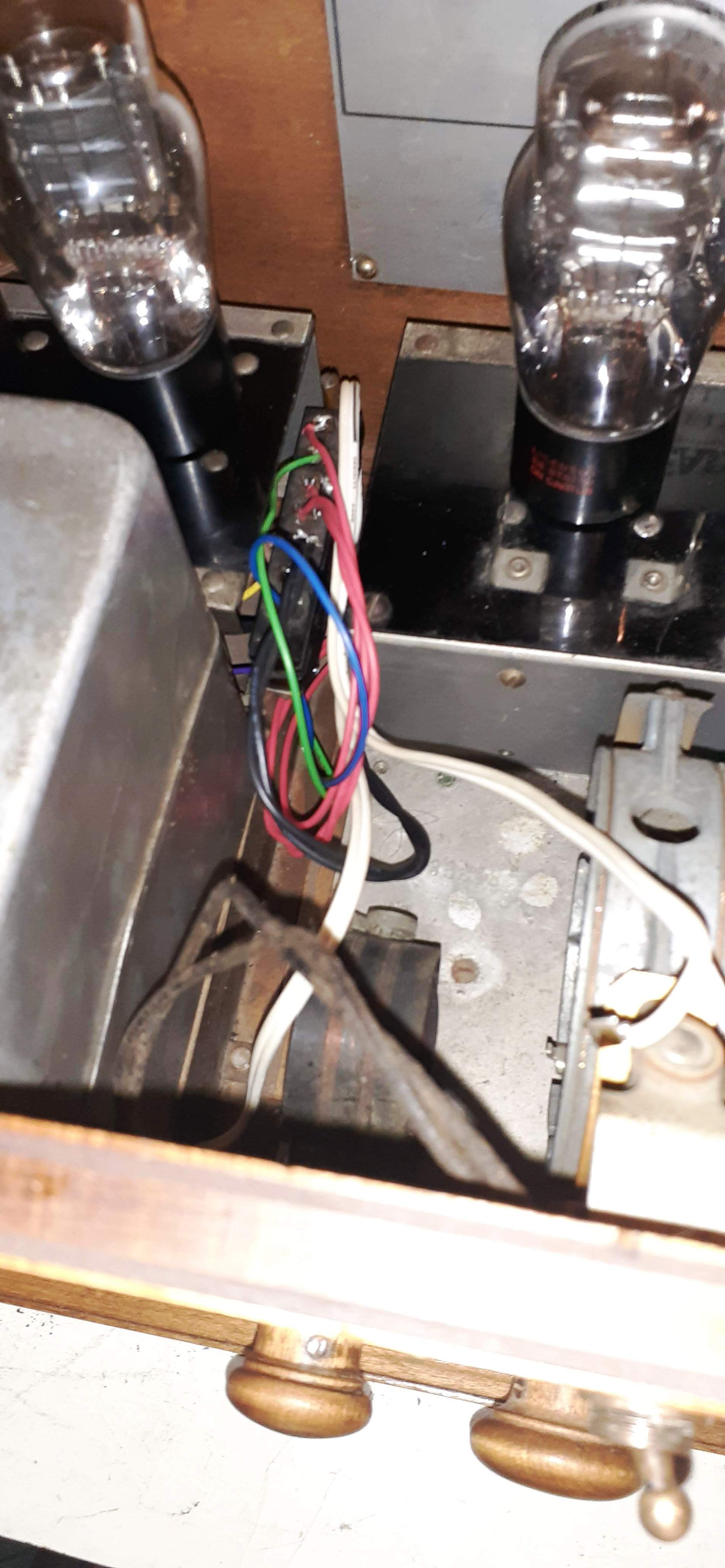
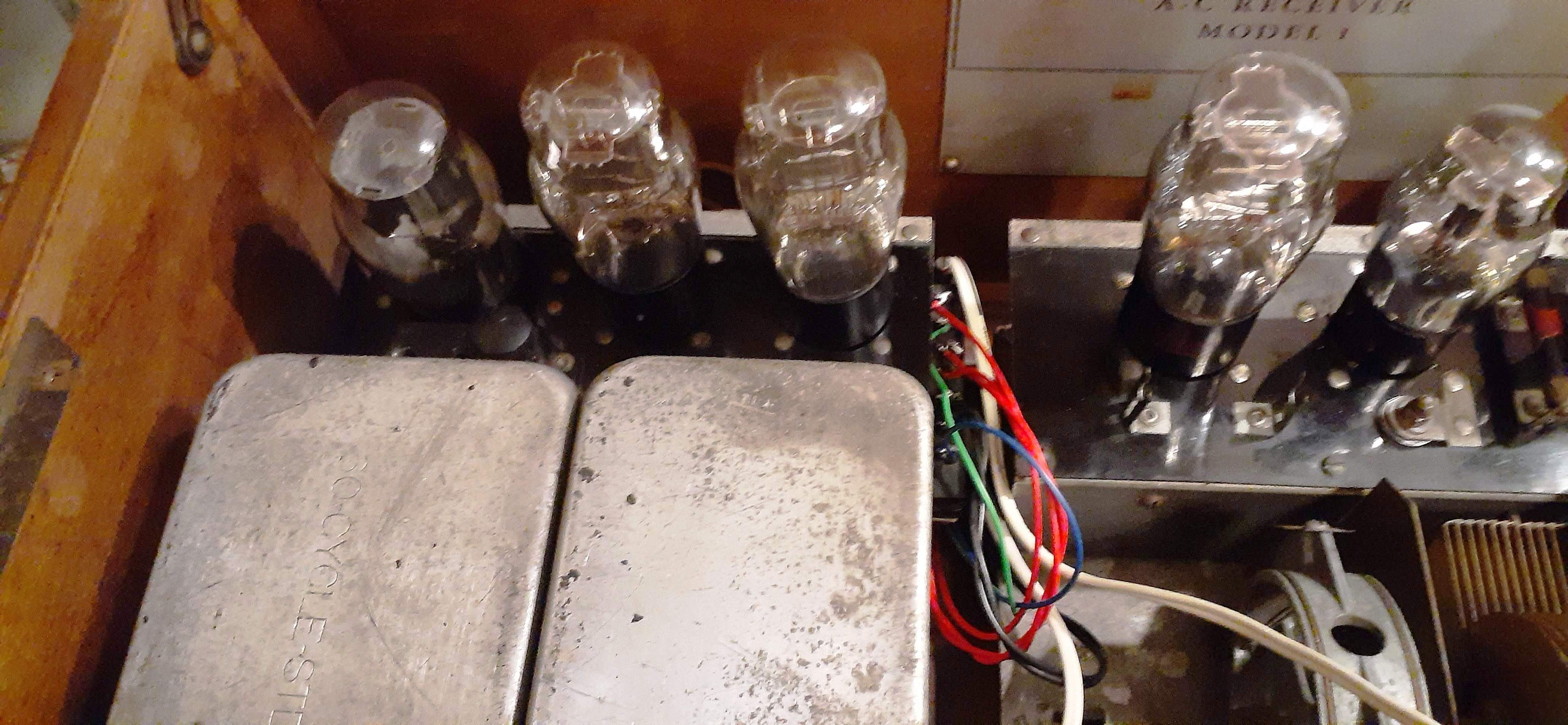
I've already replaced the old filter caps by cutting out the old ones (which couldn't be accessed to be restuffed because they were potted in tar inside an aluminum box) so I just wired the new filter caps onto the same terminal strip terminals that the old filter caps were wired to and they look fine there.
Posts: 325
Threads: 34
Joined: Dec 2019
City: Elkhart
State, Province, Country: Indiana
I'm just going to install a modern axial leaded 47k Ohm 1 Watt resistor onto the terminals below the resistor socket so that way if I do end up finding a 50K Ohm fuse style resistor I can just install it in the socket and just unhook the one underneath.
Posts: 325
Threads: 34
Joined: Dec 2019
City: Elkhart
State, Province, Country: Indiana
I've finished rewiring the radio's power supply circuit and I powered it up at first without any tubes in it and it drew about 1.2 Amps and with the tubes in it drew about 0.2 amps and the B+ voltage with the tubes in it (not including the tuner section) about 160 VDC which is about right and the High Voltage winding was producing about 400 VAC which is about right, and there wasn't any smoke or sparks or arcing so I think we're off to a good start, just waiting for my resplacement speaker to come in the mail for the speaker for this radio.
Posts: 325
Threads: 34
Joined: Dec 2019
City: Elkhart
State, Province, Country: Indiana
OK so an update:
I just finished installing the new Plate resistor under where the old one was (it was attached across the terminals for the resistor mount that is ontop of the chassis), and then I hooked the tuner portion of the radio up to the power supply and installed the rest of the tubes into the radio (the ones for the tuner section) and powered it on and monitored the B+ voltage and it was nearly spot on at around 89.7 VDC once everything warmed up.
So it seems that everything is working as it should!


Now all that's left is to wait for my replacement speaker to come in the mail and test the radio out to see if it picks any stations up.


Posts: 325
Threads: 34
Joined: Dec 2019
City: Elkhart
State, Province, Country: Indiana
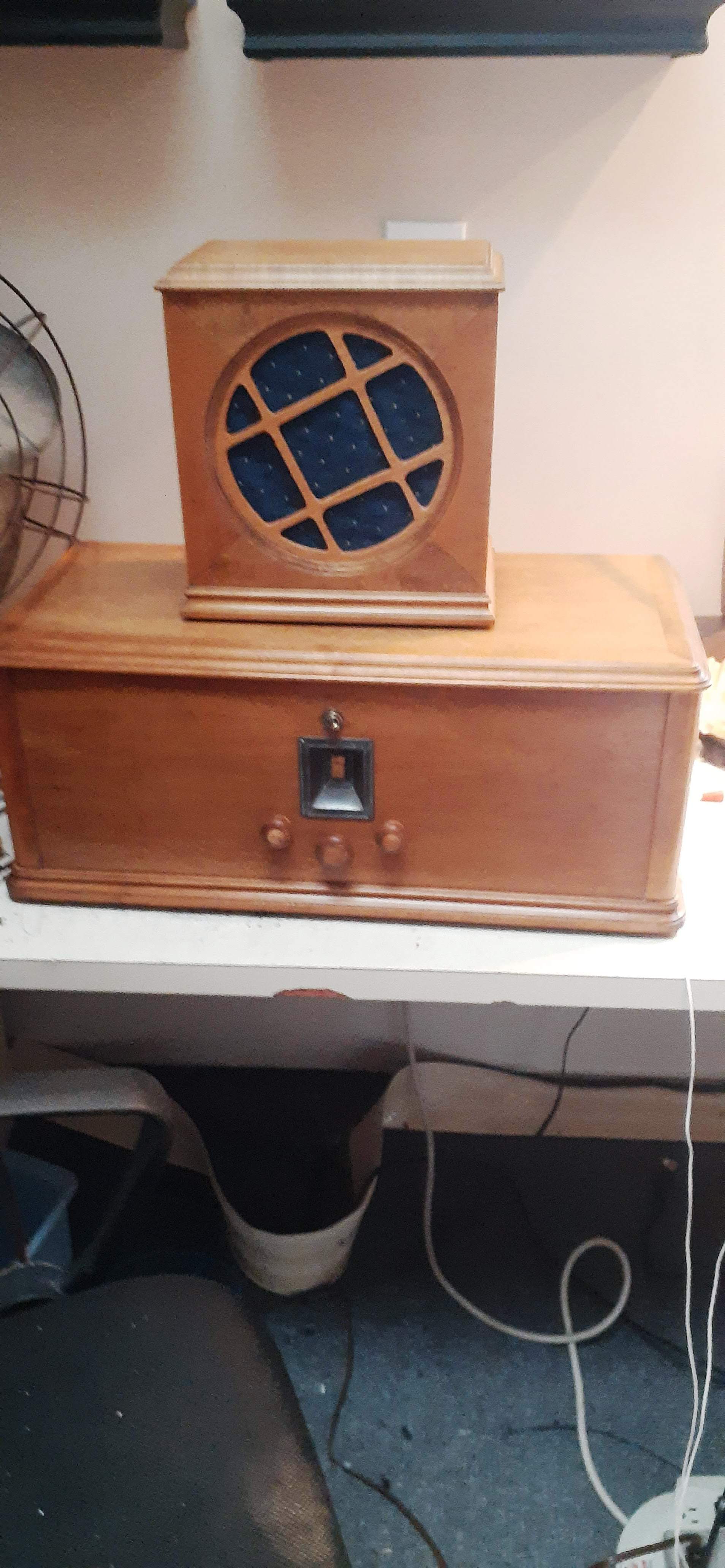
It is finally finished! I just finished putting the radio back together and finished fixing the speaker and I made a YouTube Video showing the radio working, I also to after shots of the radio.
Enjoy!
Levi
[Video:
https://youtu.be/P-1rXkXH_IY]


Posts: 1,475
Threads: 69
Joined: Nov 2012
City: Kansas city, MO.
Very nice job and it sounds good too.


![[-] [-]](https://philcoradio.com/phorum/images/bootbb/collapse.png)


