Power supply design needed from master designer Terry
Posts: 1,531
Threads: 242
Joined: Sep 2012
City: West Bend, Wisconsin
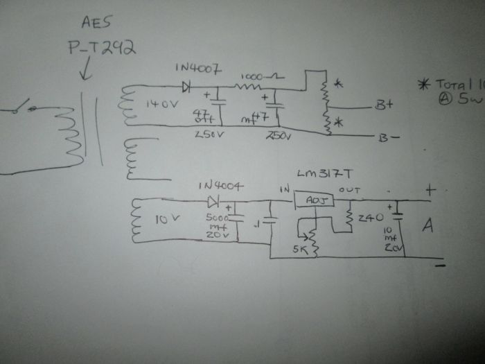
About 5 years ago, Terry supplied me with a great power supply for a Philco Farm set...

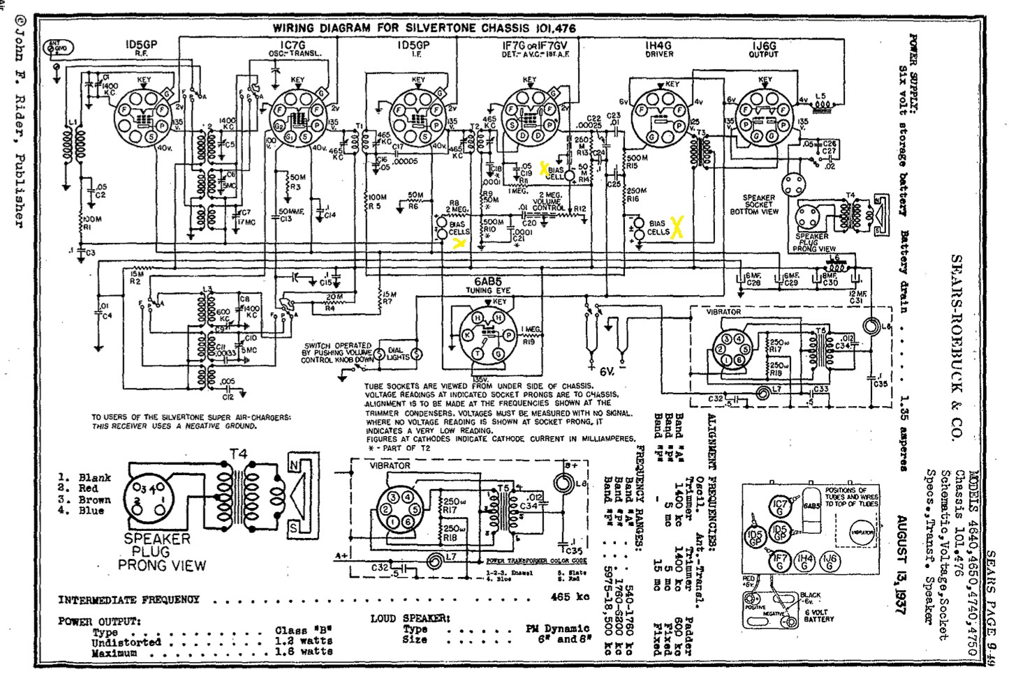
This past Spring I was gifted a Silvertone model 4640 battery set and thought I'd be able to build another power supply like the above for it. There's just one problem, as you'll see on the schematic below... (besides the 5 bias cells I marked in yellow)

This set uses a vibrator supply for the "B". So unless I eliminate that vibrator supply altogether, this power supply design won't work.
I'm leaning towards just eliminating the vibrator supply box altogether, and using the above supply design from Terry. That would eliminate the troublesome vibrator (which may not be any good anyhow).
If I'm able to restore the vibrator supply I guess I just need to feed the radio 6VDC starting with a 120:6 filament transformer? Does AES have one of these?
Maybe Terry can sketch something up or revise the above that would work with this radio? (Happy New Year, Terry!)
Thanks!
Greg V.
West Bend, WI
Member WARCI.org
Posts: 7,303
Threads: 269
Joined: Dec 2009
City: Roslyn Pa
Oh past has come to haunt me!!!!!!!!!!!!!!!!
I think we can use the bottom half of the old design but change the regulator and transformer. The bias cells your better off using batteries. Using long wires to the p/s may cause hum pickup and it doesn't seem that they all have a common + so that adds a bit more difficulty to the problem.
When my pals were reading comic books
I was down in the basement in my dad's
workshop. Perusing his Sam's Photofoacts
Vol 1-50 admiring the old set and trying to
figure out what all those squiggly meant.
Circa 1966
Now I think I've got!
Terry
Posts: 7,303
Threads: 269
Joined: Dec 2009
City: Roslyn Pa
For the bias batteries you could try to rejuvenate them by injecting them w/distilled water. Or use watch batteries to replace them. Or depending on where they are in the circuit they may be able to be replaced w/high value a resistor.
Replace the LM317T w/a LM317K same device but in a to-3 package and has a 3amp max rating vs the 1.5 of the 317T. You'll need the insulators, paste, and a heat sink to mount it. Power transformer can be a 12v@ 2 or 3amp and a diode to match. The 1N400* are rated @ 1amp on a good day. 1N5401 is good 100v @ 3A. The rest is the same as the lower section w/o any of the hv stuff.
When my pals were reading comic books
I was down in the basement in my dad's
workshop. Perusing his Sam's Photofoacts
Vol 1-50 admiring the old set and trying to
figure out what all those squiggly meant.
Circa 1966
Now I think I've got!
Terry
(This post was last modified: 01-02-2022, 12:21 PM by Radioroslyn.)
Posts: 330
Threads: 30
Joined: Aug 2017
City: Hay Lakes, Alberta,Canada
I'm looking forward to seeing the design! 
Terry, this will get the brain functioning again after all the eggnog and Christmas goodies...
Posts: 7,303
Threads: 269
Joined: Dec 2009
City: Roslyn Pa
To be honest haven't celebrated Christmas, Daughter's birthday, or New Year yet. Due to family timing it's happening on Saturday. A whole lot of catching up to do on Sat along with wrapping and some baking beforehand.
The p/s is pretty rootamentary. I like the '317 regulators they're really handy and can clean up your slightly ripply dc. Will take up to 37vdc at it's input and regulate it down to 1.5v. I wouldn't recommend starting off with that high of an input voltage to go down to 1.5v that's a lot dissipation for the regulator.
When my pals were reading comic books
I was down in the basement in my dad's
workshop. Perusing his Sam's Photofoacts
Vol 1-50 admiring the old set and trying to
figure out what all those squiggly meant.
Circa 1966
Now I think I've got!
Terry
(This post was last modified: 01-02-2022, 12:58 PM by Radioroslyn.)
Posts: 1,531
Threads: 242
Joined: Sep 2012
City: West Bend, Wisconsin
I feel like the ghost of Christmas past, Terry....even though the other power supply wasn't done around Christmastime.
Here's the full schematic which may be easier to read than the screen capture I posted:
http://www.nostalgiaair.org/PagesByModel...017167.pdf
I thank you very kindly for the ideas to modify the power supply design to accommodate the vibrator supply, and may have to go that route, but I'd like to consider this first...
After the success with the last power supply in 2017, and while everything was still available. I purchased a second set of components figuring I'd be able to use it for another farm set. So basically I have everything here to build the original one again and am wondering if there's a way to use that on this Silvertone by eliminating that neat little metal box that contains the vibrator supply?
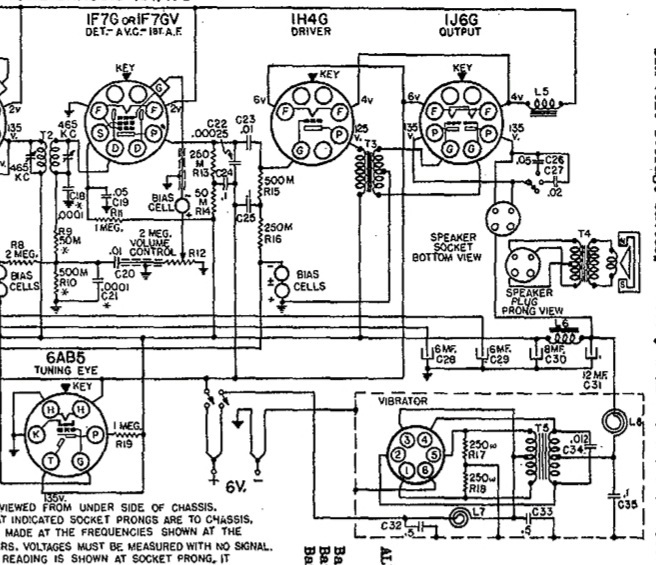
Here's a crop of that section of the schematic:

I'm only seeing 3 wires coming out of that metal box. One is grounding the box to the Negative - cable, another is going to the off/on switch, and the third going to the positive side of the 12 MFD electrolytic and to L6 (and points beyond). In theory it looks simple enough to eliminate but of course may not be.
So to pose an overly simple question to a complicated problem, (but one that would make it a whole lot easier for me to understand), with the box eliminated, where is the best place to connect A + & A - and B + and B - using your original power supply?
I'll wait for you to stop laughing!
Greg V.
West Bend, WI
Member WARCI.org
Posts: 7,303
Threads: 269
Joined: Dec 2009
City: Roslyn Pa
If you did find the P-T292 transformer, I read that they have been discontinued for sometime now. It should work fine. The P-T292 is pretty stout and can deliver the current required power you set. Just readjust the A voltage to 6v. Connect the B+ to the top of the voltage divider for maximum voltage.Connect the A- and B- together they connect to the chassis. A+ connects to the off/on sw and B+ connect to C31.
When my pals were reading comic books
I was down in the basement in my dad's
workshop. Perusing his Sam's Photofoacts
Vol 1-50 admiring the old set and trying to
figure out what all those squiggly meant.
Circa 1966
Now I think I've got!
Terry
(This post was last modified: 01-02-2022, 02:24 PM by Radioroslyn.)
Posts: 1,531
Threads: 242
Joined: Sep 2012
City: West Bend, Wisconsin
Yes, I got lucky and found a P-T292 transformer so that's going to be a big help. So just use the 5K pot and dial it down to 6V?
And just to verify my brain is still functioning in 2022:
A - & B - are both to chassis ground?
A + to off / on switch?
B + to the positive side of the 12 MFD e-cap (C31)?
That should work just fine with the vibrator supply disconnected (I'll probably leave the box bolted on top of the chassis for "show") and will work with the existing PS design from 2017.
Tonight I freed up the tuning mechanism which was froze tight. A few well placed small squirts of Kroil did the trick.
I also took out the 5 bias cells and checked them for voltage. I got nothing on them. So I boiled some water, and dropped them in. Yes, they bubbled like crazy for a few seconds. I left them cool in the water a bit, took them out and set them on a paper towel until the water disappeared inside. Then rechecked them. Each now measured .87 v. So it did something. Not quite the 1.5 v I was expecting but better than nothing.
Greg V.
West Bend, WI
Member WARCI.org
Posts: 7,303
Threads: 269
Joined: Dec 2009
City: Roslyn Pa
Yes.....
When my pals were reading comic books
I was down in the basement in my dad's
workshop. Perusing his Sam's Photofoacts
Vol 1-50 admiring the old set and trying to
figure out what all those squiggly meant.
Circa 1966
Now I think I've got!
Terry
Posts: 1,883
Threads: 120
Joined: May 2008
City: Omak
State, Province, Country: WA
Hello Greg,
I can't wait to see how your power supply turns out !
Sincerely Richard
Posts: 1,531
Threads: 242
Joined: Sep 2012
City: West Bend, Wisconsin
Terry,
What are we shooting for on the B + with the two voltage divider resistors? Is it still 90v for this set? I'm seeing 135v on the two plates for the 1J6 output tube on the schematic which leads me to believe it may require more than 90.
Last time we were looking at two resistors adding up to 10K to make up the voltage divider.
Last time I found if I used a 4K from the + side of the 47 mfd to B +, and a 5K between the B + & B -, I got 94 volts. But that was without a load. Once I tried it on the radio, it dropped down to 76 volts, so apparently I need a higher value resistor than 5K between the B + & B -, and a smaller value resistor than 4K from the + of the 47 mfd to B + in order to get 100v without a load.
Greg V.
West Bend, WI
Member WARCI.org
Posts: 4,908
Threads: 54
Joined: Sep 2008
City: Sandwick, BC, CA
I would just disconnect the vibrator power supply from the rest of the radio, leaving the parts in place, and build an off board one connected to the main chassis with a four conductor cable, if there is room inside the cabinet. There are two reasons for this: It leaves the option to a future owner to return the radio to the way it left the factory. It also allows more flexibility with what parts you can use to build the power supply, and what you can build it on, and eliminates the problem of introducing an AC hum from added transformers, or wiring, under the chassis. I think this radio, like my Stewart Warner vibrator radio, had the tubes connected in a series-parallel arrangement to accommodate the 6.3 volt supply, for this same reason they used independent bias cells under the chassis as my S.W did. I also would not be surprised if this set was built by Stewart Warner for Sears, though they were not the only contractor Sears used outside Colonial.
Regards
Arran
Posts: 7,303
Threads: 269
Joined: Dec 2009
City: Roslyn Pa
We should be able to get close to 135v out of the B supply. But I wasn't sure if that configuration was going to do it. Plan B is disconnect the hv winding from the 1N4007 and the B- rail. Remove 1N4007 and replace with a full wave bridge rectifier.
It will looks like this https://www.digikey.com/en/products/deta...gJKh_D_BwE Easy to connect two squiggly lines on the top go to the ac and there are a + & - connection which will go to the 47mf cap. I don't think this will exceed the 160v rating of the input cap. Or if it does you'll be the first to know[Image: https://philcoradio.com/phorum/images/sm...on_eek.gif] You may want to disconnect one end of the input cap and connect another 47mfd 160 job in series with it this with give 23 1/2mfd 320v
The pic is the first one that came up in a search. There are 100's different ones something around 400v@1A is plenty. I salvage them off of old computer p/s boards. Just have to look up the p# to see if it has a high enough voltage rating. Most of the time they do.
When my pals were reading comic books
I was down in the basement in my dad's
workshop. Perusing his Sam's Photofoacts
Vol 1-50 admiring the old set and trying to
figure out what all those squiggly meant.
Circa 1966
Now I think I've got!
Terry
(This post was last modified: 01-04-2022, 01:31 PM by Radioroslyn.)
Posts: 1,531
Threads: 242
Joined: Sep 2012
City: West Bend, Wisconsin
That's what I'm planning on doing, Arran. Especially since I verified that the vibrator supply actually (amazingly) still works. After recapping I hooked it up to a 6v gel cell battery I had here (which, in turn, was hooked to a battery charger). Not the most ideal set up but for a brief test it showed me that the radio does play, quite well too despite the added buzz between stations from the charger. But I had to leave the eye tube out which was too much of a load for that little battery.
Also amazingly, the original eye tube is still at least 80 % bright, and the 1 meg resistor that's usually always open, still measured 1 meg. Original dial bulbs still both light too. You have to push down on the volume control knob to light the lights.
Greg V.
West Bend, WI
Member WARCI.org
Posts: 1,531
Threads: 242
Joined: Sep 2012
City: West Bend, Wisconsin
Thanks, Terry. I think I may have one of those FW bridge rectifiers here yet too.
But I'm thinking of going with plan A first to see if I can get 135v out of the B supply on the existing design.
For that, I need to borrow your math skills again...
What would the total resistance needed be for the two voltage divider resistors to get to 135v? For 90v you had figured 10K.
Using this calculator: https://ohmslawcalculator.com/voltage-di...calculator
and entering 140 as the voltage source, R1 (or from the + side of the 47 mfd to B +) would be a 50 ohm, and R2 (or between B + & B -) would be a 10K ohm resistor to get 139 volts output.
Now obviously that's without a load so it probably will drop under 135 in circuit but may be enough to power the radio.
Greg V.
West Bend, WI
Member WARCI.org
Users browsing this thread: 1 Guest(s)
|
|
Recent Posts
|
|
Model 80 Antenna Issue?
|
| Thanks Gary and Rod.
I also found an article in the Philco Repair Bench under Service Hints and Tips, about installi...Hamilton — 12:32 PM |
|
Model 80 Antenna Issue?
|
| Hello Hamilton, here is a little information found in our Philco Radio Library at the bottom of the Home page. Hope it ...GarySP — 11:28 AM |
|
Model 80 Antenna Issue?
|
| I did as you suggested and touching the middle of the volume control did nothing so the coil has to be rewound. Any idea...Hamilton — 10:19 AM |
|
1949 Motorola 5A9M
|
| This would be the second portable in the "other radios" forum where I have a similar one in my collection. I h...Arran — 12:41 AM |
|
Looking for any info: 1977 Ford-Philco Console Hi-Fi Turntable and Radio
|
| Hi PittsburgTost.
The record changer looks like a Garrard or BSR (Likely Garrard). The spindles just pull out and pu...MrFixr55 — 11:57 PM |
|
Looking for any info: 1977 Ford-Philco Console Hi-Fi Turntable and Radio
|
| Hello PittsburghToast ,
Welcome aboard and it looks like gary may have something for you !
now if I dig through my se...radiorich — 11:35 PM |
|
Model 80 Antenna Issue?
|
| You are kind of on the right path. You can touch the grid cap of the Detector/Oscillator 36 tube. I'm expecting a respon...RodB — 08:48 PM |
|
Looking for any info: 1977 Ford-Philco Console Hi-Fi Turntable and Radio
|
| Welcome to the Phorum, PittsburghToast! I found an old thread that my interest you regarding the quality and worth of P...GarySP — 08:48 PM |
|
Looking for any info: 1977 Ford-Philco Console Hi-Fi Turntable and Radio
|
| Welcome to the Phorum!
:wave:
We do not have anything on that unit in our digital library. There is a Sam's Photof...klondike98 — 08:47 PM |
|
Model 80 Antenna Issue?
|
|
I’ve replaced all the caps and resistors and the radio is working but minimal volume unless I put my hand near the re...Hamilton — 08:24 PM |
|
Who's Online
|
| There are currently no members online. |

|
 
|


![[-] [-]](https://philcoradio.com/phorum/images/bootbb/collapse.png)


