Posts: 1,531
Threads: 242
Joined: Sep 2012
City: West Bend, Wisconsin

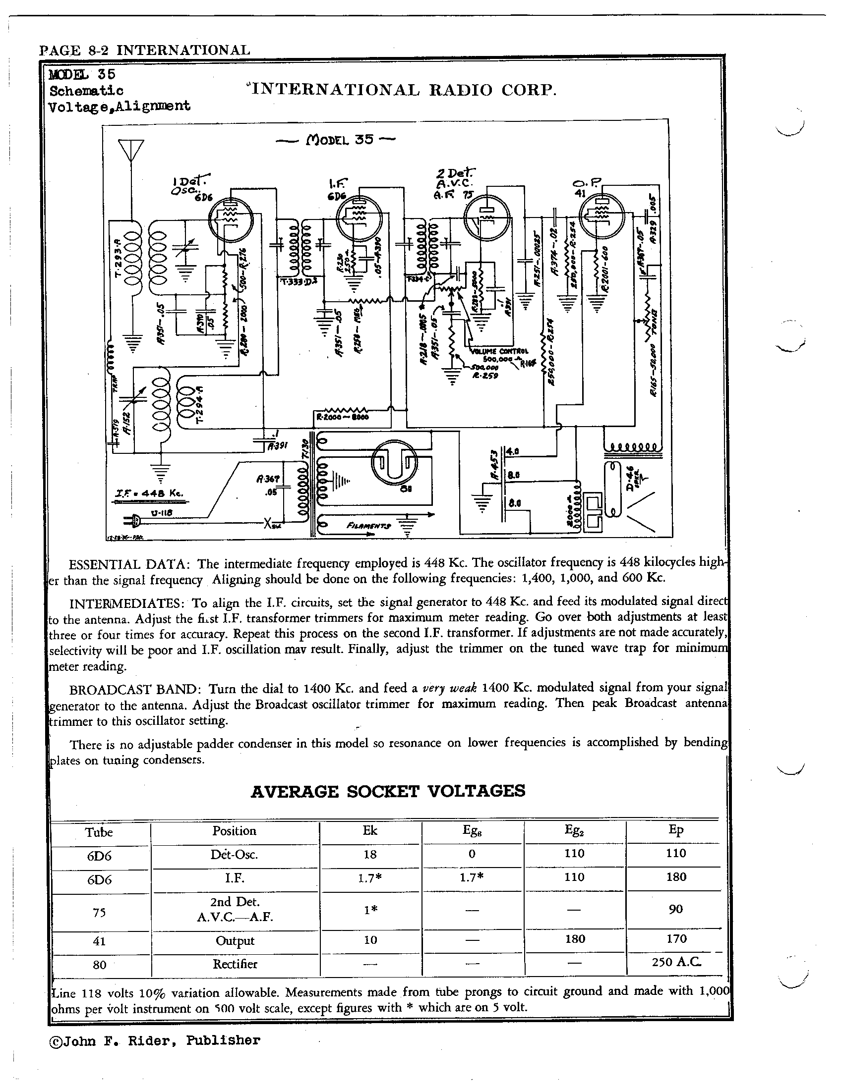
Have the radio recapped, checked all the resistors, traced out all the coils and verified continuity but found I have an open primary on the 2nd IF between the 6D6 IF tube and the 75 tube. I removed the can and checked out the coil and all the external connections are still present and connected so the break must be in the coil winding itself. Short of trying to rewind the coil...which I really don't want to attempt...is there a way to bypass that open primary? I was getting -6 volts on the plate of the 6D6 IF tube instead of the 180 volts it calls for which was the red flag, otherwise all other voltages are present, albeit a bit high.
Both IF cans measured 20 ohms on the primary and secondary sides (well just the secondary on the 2nd IF, of course). I found an IF from a 1936 5 tube Crosley I parted out that has 28 ohm primary and secondary windings, so I gater wired that in just to see if it made a difference. I now have 182 volts on the plate of the 6D6 IF tube, but otherwise the radio is dead. No noise from the center of the volume control, however on the plate of the 75 tube I have a somewhat weak output buzz that's controllable by the volume control. Otherwise there's no buzz touching the grid caps of any of the 6D6's or the 75 tube.
Everything that could go wrong on this radio did. Open speaker field coil, fried power transformer, and now open IF can. But I'm determined not to take if off life support!
Greg V.
West Bend, WI
Member WARCI.org
Posts: 7,303
Threads: 269
Joined: Dec 2009
City: Roslyn Pa
Sounds like you have more than just the bad IF transformer. If all is well you should get a loud buzz at the cap of the 75 tube. That needs to be sorted.
The resistance of the ift means very little. What we need to know is the resonant frequency. The set your working on is 448kc but what about your parts set?
Remember the farm p/s? Can't properly troubleshoot the IF stage using 12" clip leads connecting things. It detunes the circuit and allows for stray pickup.
You might want to remove the 6D6 IF tube till you get the plate voltage working. Not having plate voltage but having voltage on the screen grid can damage the tube.
When my pals were reading comic books
I was down in the basement in my dad's
workshop. Perusing his Sam's Photofoacts
Vol 1-50 admiring the old set and trying to
figure out what all those squiggly meant.
Circa 1966
Now I think I've got!
Terry
Posts: 1,531
Threads: 242
Joined: Sep 2012
City: West Bend, Wisconsin
You're absolutely right about not using the gater wires to connect things and I only did it momentarily because on the replacement IF I didn't know which side is primary and which is secondary...or if it even matters ...and wanted to avoid soldering and unsoldering but yes I agree and learned from the farm set that it is a bad idea. Will solder it in later this afternoon when I work on it again.
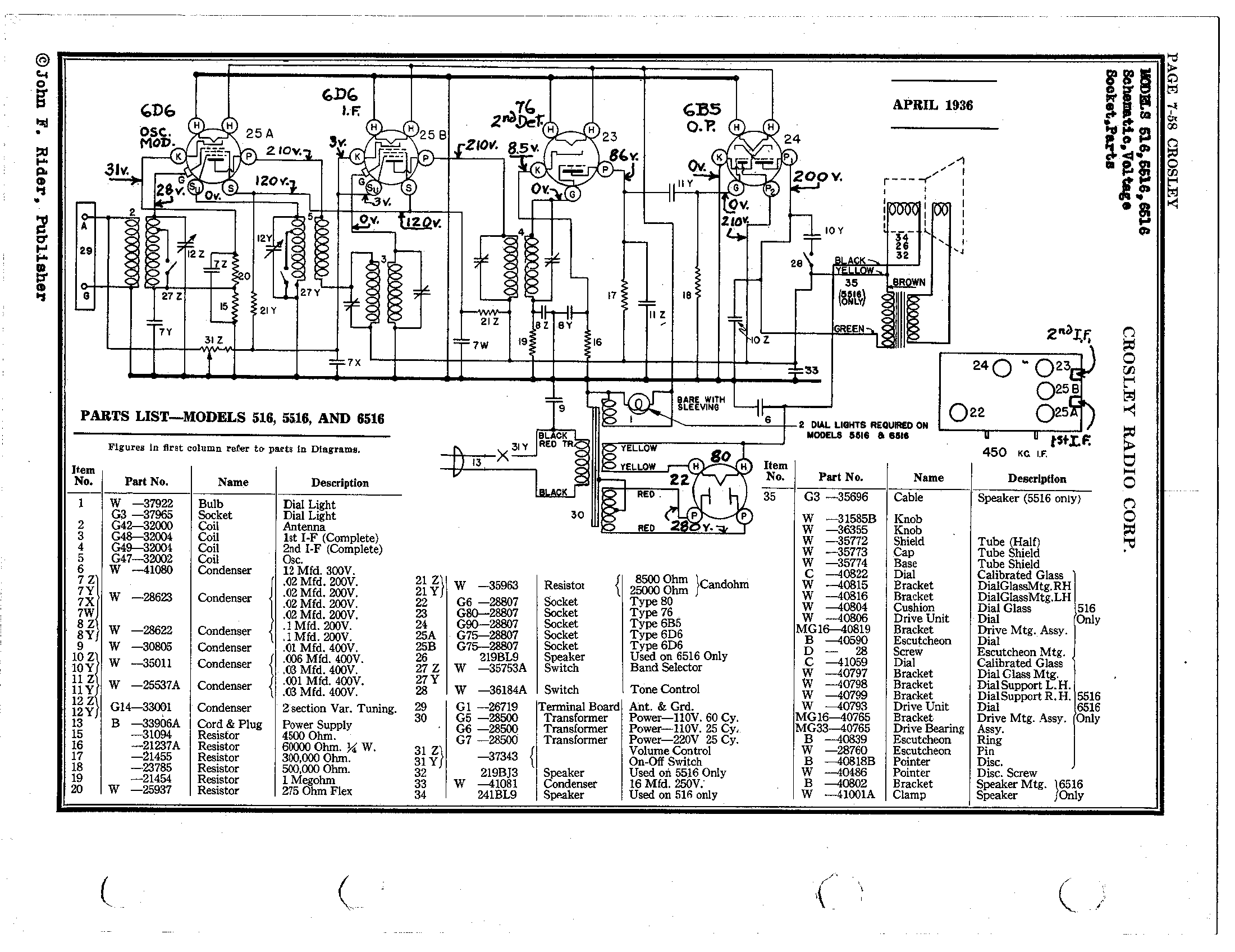
The replacement IF is from a Crosley model 516, and the resonant frequency is 450kc, where as the Kadette should be be 448kc. That's about as close as I can find. Here's the schematic for the Crosley for comparison:

Greg V.
West Bend, WI
Member WARCI.org
Posts: 7,303
Threads: 269
Joined: Dec 2009
City: Roslyn Pa
If both windings are good on the replacement ift you shouldn't have a problem retuning it to 448kc. That should solve the IF problem so far.
Even at 455kc could be lowered to 448 by adding some capacitance across each winding.
When my pals were reading comic books
I was down in the basement in my dad's
workshop. Perusing his Sam's Photofoacts
Vol 1-50 admiring the old set and trying to
figure out what all those squiggly meant.
Circa 1966
Now I think I've got!
Terry
Posts: 1,151
Threads: 47
Joined: Feb 2015
City: Roseville, MN
Hi Greg,
It might be more important to get the audio working first then tune the IF transformers to 448kHz. Like Terry says you may have to experiment with the 2nd IF resonance by adding a 10pf(or so) cap to each winding. Or you might get lucky and have enough signal without the caps.
Posts: 13,776
Threads: 580
Joined: Sep 2005
City: Ferdinand
State, Province, Country: Indiana
Those 1930s-1940s IF transformers usually had a fairly wide range of tuning, so you will likely be able to tune transformers designed for a 455 kc IF down to 448 kc without issue.
--
Ron Ramirez
Ferdinand IN
Posts: 1,531
Threads: 242
Joined: Sep 2012
City: West Bend, Wisconsin
I'm getting used to the feel of egg on my face....
I'm ready to admit my embarrassing assumption that proved to be why the replacement IF can wasn't working with the clip leads. With an AM only radio and two knobs (besides the tuner), I figured it was off/on/volume and a separate knob for the tone control. WRONG! Studying the schematic closer I couldn't understand why one side of the "volume" control had nothing connected to it, when it clearly shows there should be. Then the light bulb went on...it was off/on/tone and a SEPARATE volume control! So with the volume control apparently turned all the way down it makes sense why the radio was silent! Lesson learned...try ALL the knobs before assuming the worst! The good news is the radio now plays great after an alignment, and that left over IF from the 1936 Crosley 516 was a perfect donor for the Kadette 
Greg V.
West Bend, WI
Member WARCI.org
Posts: 1,824
Threads: 114
Joined: Jul 2014
City: Sneedville, TN
Congratulations Greg ! That kind of thing happens to the best of us. Live and learn.
Posts: 1,151
Threads: 47
Joined: Feb 2015
City: Roseville, MN
Hey Greg, I'll have mine scrambled!!
Posts: 4,460
Threads: 423
Joined: Jun 2011
City: Boston
State, Province, Country: Massachusetts
One of our Ex Club Presidents started a thread about "goofs" we made as a testament to the fact we all make them, recently a friend brought me a cute little Emerson, found it at a job he was doing. It had a small crack, as I pressed on it a bit I broke it worse, gee thanks Boris, aaahhh errggh.... I am sure I can fix it, I pray!
Paul
Tubetalk1
Posts: 5,182
Threads: 276
Joined: Nov 2012
City: Wilsonville
State, Province, Country: OR
I've had more than one 'egg on my face' experience!
Posts: 1,531
Threads: 242
Joined: Sep 2012
City: West Bend, Wisconsin
Glad I'm not alone in having a "D'oh!" moment! 

Greg V.
West Bend, WI
Member WARCI.org
Users browsing this thread:
|
|
Recent Posts
|
|
Model 80 Antenna Issue?
|
| Thanks Gary and Rod.
I also found an article in the Philco Repair Bench under Service Hints and Tips, about installi...Hamilton — 12:32 PM |
|
Model 80 Antenna Issue?
|
| Hello Hamilton, here is a little information found in our Philco Radio Library at the bottom of the Home page. Hope it ...GarySP — 11:28 AM |
|
Model 80 Antenna Issue?
|
| I did as you suggested and touching the middle of the volume control did nothing so the coil has to be rewound. Any idea...Hamilton — 10:19 AM |
|
1949 Motorola 5A9M
|
| This would be the second portable in the "other radios" forum where I have a similar one in my collection. I h...Arran — 12:41 AM |
|
Looking for any info: 1977 Ford-Philco Console Hi-Fi Turntable and Radio
|
| Hi PittsburgTost.
The record changer looks like a Garrard or BSR (Likely Garrard). The spindles just pull out and pu...MrFixr55 — 11:57 PM |
|
Looking for any info: 1977 Ford-Philco Console Hi-Fi Turntable and Radio
|
| Hello PittsburghToast ,
Welcome aboard and it looks like gary may have something for you !
now if I dig through my se...radiorich — 11:35 PM |
|
Model 80 Antenna Issue?
|
| You are kind of on the right path. You can touch the grid cap of the Detector/Oscillator 36 tube. I'm expecting a respon...RodB — 08:48 PM |
|
Looking for any info: 1977 Ford-Philco Console Hi-Fi Turntable and Radio
|
| Welcome to the Phorum, PittsburghToast! I found an old thread that my interest you regarding the quality and worth of P...GarySP — 08:48 PM |
|
Looking for any info: 1977 Ford-Philco Console Hi-Fi Turntable and Radio
|
| Welcome to the Phorum!
:wave:
We do not have anything on that unit in our digital library. There is a Sam's Photof...klondike98 — 08:47 PM |
|
Model 80 Antenna Issue?
|
|
I’ve replaced all the caps and resistors and the radio is working but minimal volume unless I put my hand near the re...Hamilton — 08:24 PM |
|
Who's Online
|
| There are currently no members online. |

|
 
|


![[-] [-]](https://philcoradio.com/phorum/images/bootbb/collapse.png)


