Halson model 610 electrolytics
Posts: 1,531
Threads: 242
Joined: Sep 2012
City: West Bend, Wisconsin
I'm having some difficulty deciphering the "condenser box" on top of the chassis and am wondering if I have another pair of eyes verify the polarity of the 3 e-caps and their connection points?
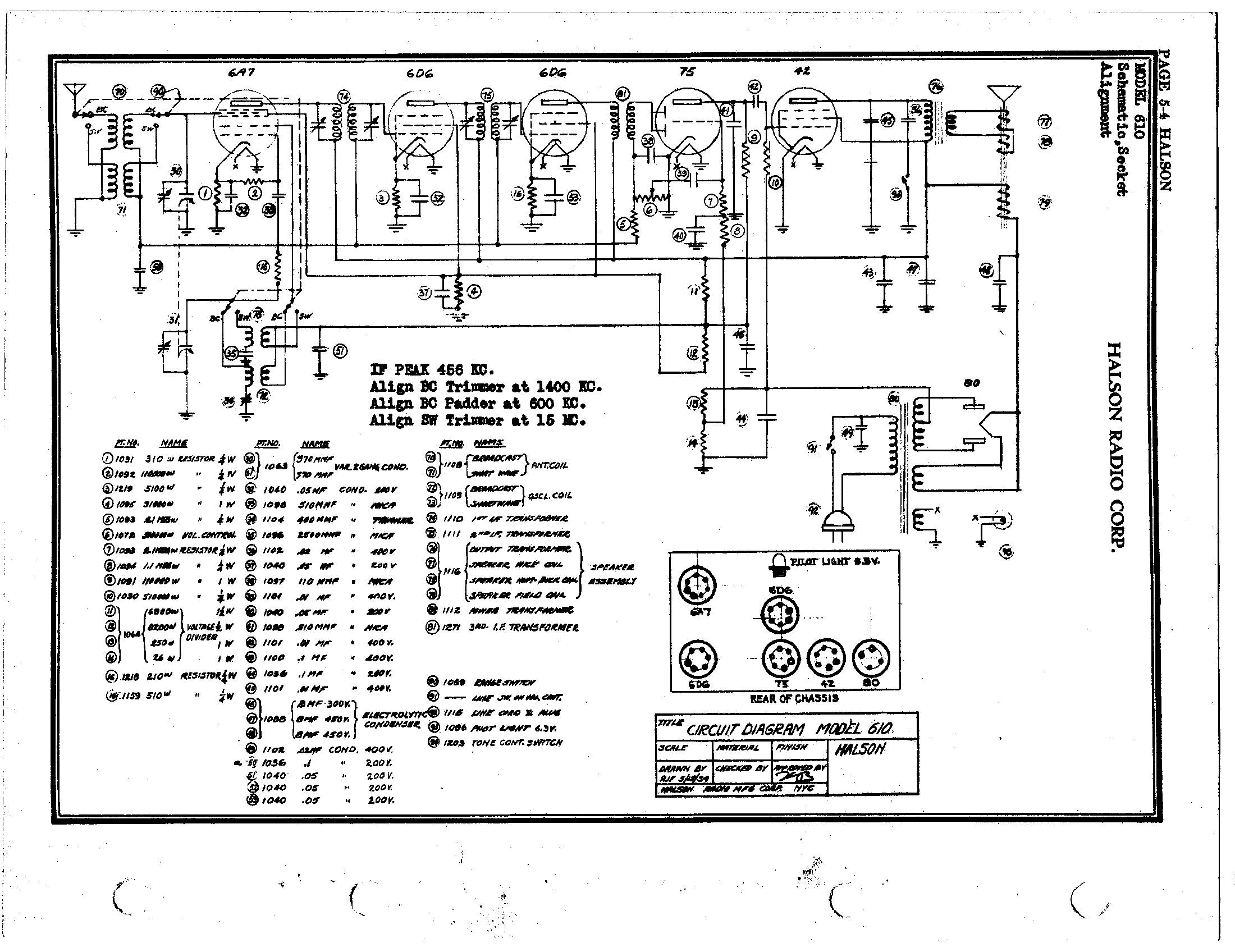
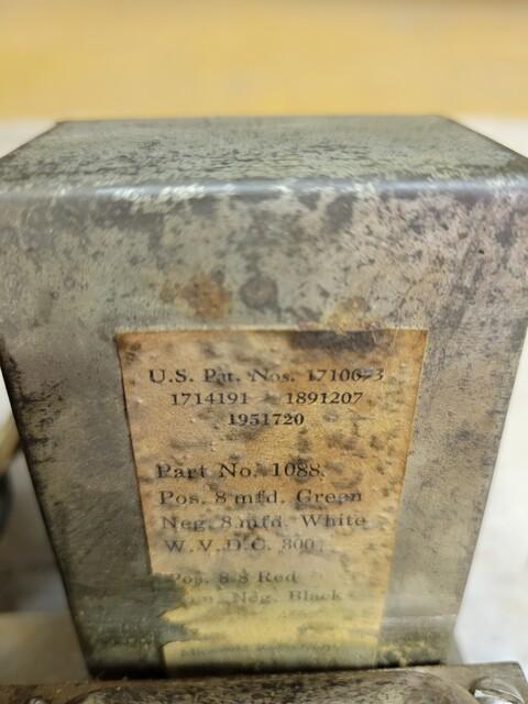
The schematic is a bit hard to read but it appears there are just three 8 mfd caps, #46, 47 and 48. Do all of the negatives go to chassis ground? The label on the box reads:
Pos 8 mfd....Green
Neg 8 mfd....white
and then
Pos 8-8 ... Red
Com Neg... black
The white wire was connected to chassis ground, but all the other wires coming out of the box were cut and so I have no idea where the black wire was supposed to be connected. Someone apparently started to recap it and gave up.
With 5 wires coming out of the box and only 3 capacitors, that tells me two are joined together somehow but I'm not seeing it on the schematic.
Supposedly there is an early and late version of this schematic and I have only found the late version. This one seems to be correct, however the 75 tube and the 6D6 tube behind it are reversed in the actual chassis from what the chassis layout shows on the schematic.

Greg V.
West Bend, WI
Member WARCI.org
Posts: 1,114
Threads: 14
Joined: Feb 2013
City: Irvington, NY
Looks like there was one 8 uF 350V cap (#46) which was isolated and connected to the green and white wires. Then there are two 8 uF 450 V caps (#47 ,#48) which have a common ground (com neg) black. So there are your 5 wires, two for #46 and three for the #47 #48 pair.
According to the schematic it appears that all the negatives connect to chassis ground but I am not sure that's correct. Normally the caps #47 and #48 would have their negatives connected to the power transformer center tap before the bias resistor #14 and #15, not to chassis ground.
Posts: 1,151
Threads: 47
Joined: Feb 2015
City: Roseville, MN
According to the schematic, the white and black go to ground, the green goes to the junction of 11 & 12 voltage divider, one red goes to the end of the voltage divider at 11 and the other red goes to pin one or four of the 80 tube.
Posts: 1,531
Threads: 242
Joined: Sep 2012
City: West Bend, Wisconsin
Here's a pic of the label on the capacitor can. This appears to be the factory original can:

There are 5 wires in total coming out of the can. Four of the 5 were clipped, only one of them, the white (or what appears to have once been white) wire is still connected to the chassis.
I tried connecting the 3 e-caps with their negatives all connected to chassis ground and positives to the connection points indicated on the schematic:
1.) positive of #46 between #11 & #12 on the candohm and to #9 the 110K ohm resistor
2.) positive of #47 to pin 3 of the 42 tube, to the output transformer, and to one side of the FC
3.) positive of #48 to the opposite side of the FC from #47, and to the filament of the 80 tube
After a full recap and out of tolerance resistor change, tracing through the schematic as I did to verify their locations (not just "shot gunning" it), all I get is a loud buzz that is not controllable with the volume. I even disconnected the high side of the volume pot so that just the wiper and grounded end are in circuit (in theory to isolate the output section from the RF) and I still get the buzz. Somehow I don't think all of the ground symbols are actual chassis ground. But which is which is the mystery
Greg V.
West Bend, WI
Member WARCI.org
Posts: 1,114
Threads: 14
Joined: Feb 2013
City: Irvington, NY
Greg, as i mentioned above, I believe there is an error in the schematic regarding the connection of the negative of caps 47 and 48. I don't think they should connect to chassis ground, but rather to the center tap of the power transformer. Connecting the negatives as shown on the schematic will cause all the ripple current to pass through the bias resistor, creating a hum.
Try disconnecting the negative lead of 47 and 48 from chassis and connect to the center tap and see if it cures the hum.
Posts: 1,151
Threads: 47
Joined: Feb 2015
City: Roseville, MN
Sounds like Mondial is going in the right direction. If that fixes the hum be sure to check the bias voltages.
Posts: 16,533
Threads: 573
Joined: Oct 2011
City: Jackson
State, Province, Country: NJ
Greg
You are turning into Kirk.
Halsons are his domain!
People who do not drink, do not smoke, do not eat red meat will one day feel really stupid lying there and dying from nothing.
Posts: 1,531
Threads: 242
Joined: Sep 2012
City: West Bend, Wisconsin
You were absolutely right, Mondial. That was it. This was about the worst schematic for errors I'd ever seen. Not just showing all the e-caps going to ground, which clearly doesn't work (I had them like that and had the non-controllable buzz), but showing the tubes in the wrong places in the chassis! To further complicate things, as found the grid cap wires were not going to the correct tubes either! This was the first radio I actually had to trace out the circuit to find which grid cap went where! So the set is playing now, but I'm not out of the woods yet. I'm dealing with an intermittent volume drop / bad connection on one of the 6D6 tube sockets that seems to be related to the goat shield. So I have that to sort through yet but at least the buzz is gone and it's receiving stations!  Thanks to all for their help and knowledge 
Greg V.
West Bend, WI
Member WARCI.org
Posts: 1,531
Threads: 242
Joined: Sep 2012
City: West Bend, Wisconsin
Haha! Mike after this first Halson, Kirk can have them! Call me unimpressed with their draftsman!
Greg V.
West Bend, WI
Member WARCI.org
Posts: 16,533
Threads: 573
Joined: Oct 2011
City: Jackson
State, Province, Country: NJ
And other things too. But they do have some interesting looking cabinets; maybe this is what attracts Kirk to them.
People who do not drink, do not smoke, do not eat red meat will one day feel really stupid lying there and dying from nothing.
Posts: 4,460
Threads: 423
Joined: Jun 2011
City: Boston
State, Province, Country: Massachusetts
They have some cute small sets, almost bot one at a meet, was sold when I went back. It was restored too, by a real good craftsman. Ray Bintliff.
Paul
Tubetalk1
Posts: 16,533
Threads: 573
Joined: Oct 2011
City: Jackson
State, Province, Country: NJ
Paul,
The Ray Bintliff? The one whose book on capacitors I have?
People who do not drink, do not smoke, do not eat red meat will one day feel really stupid lying there and dying from nothing.
Users browsing this thread: 1 Guest(s)
|
|
Recent Posts
|
|
Model 80 Antenna Issue?
|
| Thanks Gary and Rod.
I also found an article in the Philco Repair Bench under Service Hints and Tips, about installi...Hamilton — 12:32 PM |
|
Model 80 Antenna Issue?
|
| Hello Hamilton, here is a little information found in our Philco Radio Library at the bottom of the Home page. Hope it ...GarySP — 11:28 AM |
|
Model 80 Antenna Issue?
|
| I did as you suggested and touching the middle of the volume control did nothing so the coil has to be rewound. Any idea...Hamilton — 10:19 AM |
|
1949 Motorola 5A9M
|
| This would be the second portable in the "other radios" forum where I have a similar one in my collection. I h...Arran — 12:41 AM |
|
Looking for any info: 1977 Ford-Philco Console Hi-Fi Turntable and Radio
|
| Hi PittsburgTost.
The record changer looks like a Garrard or BSR (Likely Garrard). The spindles just pull out and pu...MrFixr55 — 11:57 PM |
|
Looking for any info: 1977 Ford-Philco Console Hi-Fi Turntable and Radio
|
| Hello PittsburghToast ,
Welcome aboard and it looks like gary may have something for you !
now if I dig through my se...radiorich — 11:35 PM |
|
Model 80 Antenna Issue?
|
| You are kind of on the right path. You can touch the grid cap of the Detector/Oscillator 36 tube. I'm expecting a respon...RodB — 08:48 PM |
|
Looking for any info: 1977 Ford-Philco Console Hi-Fi Turntable and Radio
|
| Welcome to the Phorum, PittsburghToast! I found an old thread that my interest you regarding the quality and worth of P...GarySP — 08:48 PM |
|
Looking for any info: 1977 Ford-Philco Console Hi-Fi Turntable and Radio
|
| Welcome to the Phorum!
:wave:
We do not have anything on that unit in our digital library. There is a Sam's Photof...klondike98 — 08:47 PM |
|
Model 80 Antenna Issue?
|
|
I’ve replaced all the caps and resistors and the radio is working but minimal volume unless I put my hand near the re...Hamilton — 08:24 PM |
|
Who's Online
|
There are currently 1463 online users. [Complete List]
» 2 Member(s) | 1461 Guest(s)
|
|
|

|
 
|


![[-] [-]](https://philcoradio.com/phorum/images/bootbb/collapse.png)


