Posts: 714
Threads: 9
Joined: Apr 2018
City: S. Dartmouth
State, Province, Country: MA
Lots of "Magic" in the Philco antennas... 
I should order one for my close-up and personal examination. I have a couple of the Consolidated antenna kits. I have replicated those. They work.
Would hope the Philco antenna is not manufacturer specific such that it may cause distortion or fading on other brands of radios 
Pliny the younger
“nihil novum nihil varium nihil quod non semel spectasse sufficiat”
Posts: 1,824
Threads: 114
Joined: Jul 2014
City: Sneedville, TN
RGK20m3, You asked, "I don’t see how the 38-690 antenna input is balanced; although it has the 3 terminals (red, black, and ground), the black and ground are connected together and are connected to chassis ground. This is how my unit is wired, and is confirmed on the schematic." If you look at the schematic for these radios...
[Image: https://64.media.tumblr.com/defa8727b5ee...a70b99.jpg]
You will notice that the connection between the black and ground is REMOVABLE. It is a metal link between the black and ground terminals on the terminal strip on the back of the chassis. This hook up is the way it is used for a single ended (long wire) type antenna. This is OPENED, detached from the black lead so that the dipole antenna goes to both ends of the primary winding of the first antenna coil when connecting to a dipole antenna. In this form, I believe the link is switched to between the ground terminal and the number 4 terminal which is connected to the center tap of the first antenna coil. Don't let the switches throw you. Look carefully at the schematic and you will see what I mean. This is a 2 band radio, so it uses two antenna coils, one for each band, and switches between them. So, YES, the dipole antenna IS balanced. There ARE unbalanced dipoles, where one leg is longer than the other to make them better at receiving on different frequencies, but this relates solely to the construction of the antenna itself, and is not what we see here.
(This post was last modified: 08-04-2022, 07:11 PM by mikethedruid.)
Posts: 62
Threads: 5
Joined: Apr 2021
City: CLARKSTON
State, Province, Country: MI
On my 38-690, the link between the black and ground terminals is a soldered wire inside the chassis; I believe this to be factory, as it is a continuous cloth covered wire from the 2 lugs to the RF sub chassis tab. From the tab there is an identical wire bonding the RF sub chassis to the main chassis.
Of course, it could have been changed at any point in the last 85 years. I do see how the antenna coil could provide a balanced input, but seems would create an issue as there is no ground reference on the circuit. Most I have seen have the coil center tapped.
Per my above post, at least one of the Philco dipole kits has a “transformer” at the mid point, and the literature for that kit (Philco Library), instructs an additional ground to this transformer if there are interference issues. The photo link that I posted shows what appears to be a balun/ transformer included in the kit. Perhaps actually an balanced to balanced matching transformer?
Not trying to argue, just trying to understand. Incidentally, that schematic you provided does not match the 38-690 schematic.
(This post was last modified: 08-05-2022, 07:24 AM by RGK20m3.)
Posts: 214
Threads: 16
Joined: May 2010
City: Kokomo, IN
the older 38-690 and 38-116 used the 37-690 37-116 tuner which were balanced the later ones were not and they less trimers
Posts: 13,776
Threads: 580
Joined: Sep 2005
City: Ferdinand
State, Province, Country: Indiana
Let's compare apples to apples.
Here is the front end of the 38-690 - the 38-116 Code 125 front end is identical:
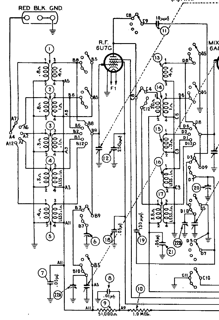
The link Chas posted in post #25, page 2, this thread shows (about halfway down the page) one side of the dipoles being grounded. This would also be the case with the 38-690 and 38-116 Code 125. In fact, if you study many of the schematics of 1938 Philco models, you will find that models 38-1, 38-2, 38-3, 38-4, 38-7, 38-8, 38-9, and 38-10 have similar front ends, all of which were advertised as being "designed for the Philco High Efficiency Aerial".
Feel free to discuss further. No arguing. Discussion is ok. Arguing is definitely not ok.
--
Ron Ramirez
Ferdinand IN
Posts: 62
Threads: 5
Joined: Apr 2021
City: CLARKSTON
State, Province, Country: MI
I suspect that later versions of the High Efficiency Aerial (40-5922) included a balun for the later (unbalanced) tuners. Perhaps the earlier kits were simpler and for early balanced inputs?
(This post was last modified: 08-05-2022, 04:47 PM by RGK20m3.)
Posts: 1,824
Threads: 114
Joined: Jul 2014
City: Sneedville, TN
Looking at the schematic posted, using a dipole on this circuit, with the black terminal permanently connected to CHASSIS ground, would only make sense if, when using a dipole, the chassis was NOT EARTH grounded, but allowed to float, in which case the antenna would be balanced. If earth ground were also connected to the GND terminal, it would defeat the whole purpose of 1/2 the dipole and turn it into a long wire half the length of the whole antenna. Perhaps careful study and reading from the various parts of an actual antenna would help answer these questions.
Posts: 337
Threads: 13
Joined: Apr 2019
City: Greenwood
State, Province, Country: Delaware
Sorry been busy here lately, but the Antenna Kit came Thursday, the 4th.
First impressions are that someone started to install it and quit, as one of the porcelain tubes looked used, while the other is still wrapped in paper. Also, one of the eggs look to have been dropped, as there is a chip (but is still usable).
The weight of each Leg seems to be slightly different; Leg 1 coil was .40 lbs. while Leg 2 coil was .48 lbs.
I measured the coils one at a time on a digital scale, first one side then the other while holding off the rest of the mess.
I’ve also taken some basic measurements as you can see on my print.
So, this unit will be disassembled. I can’t help myself; I must take things apart!
Regards,
Simon
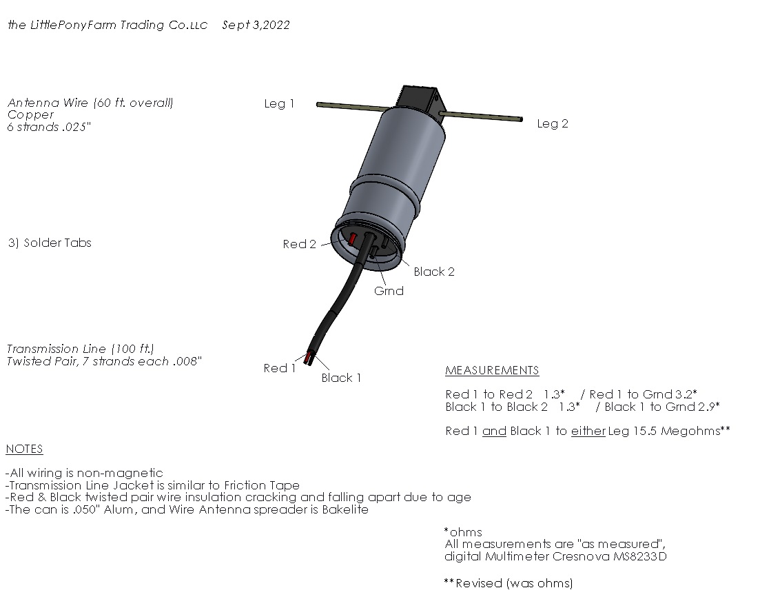
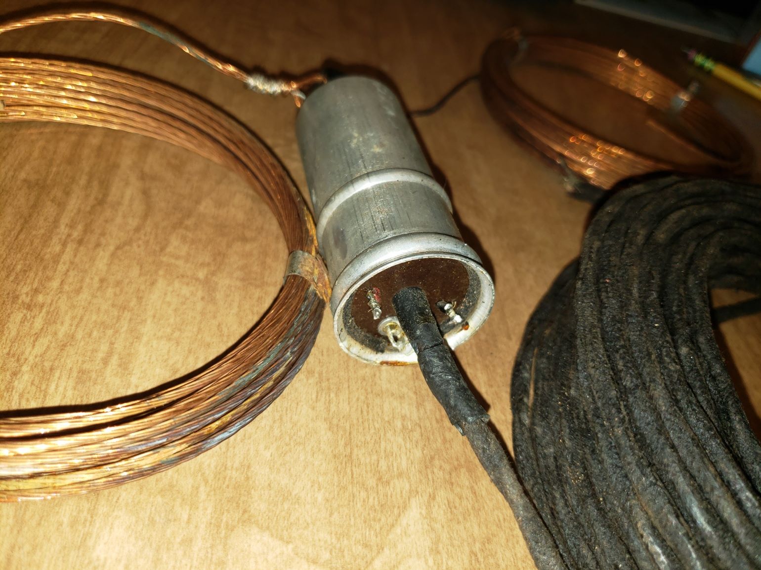
(This post was last modified: 09-03-2022, 02:59 PM by Simon Wa3uay.)
Posts: 1,264
Threads: 32
Joined: Jan 2014
City: Wellborn Florida
Glad you got it, nice find. David
Posts: 337
Threads: 13
Joined: Apr 2019
City: Greenwood
State, Province, Country: Delaware
Thanks David;
Well I took it apart. There is a coated wire circle clip that comes off first, but I find pushing it out requires the heat gun, and a pair of eagle beaks.
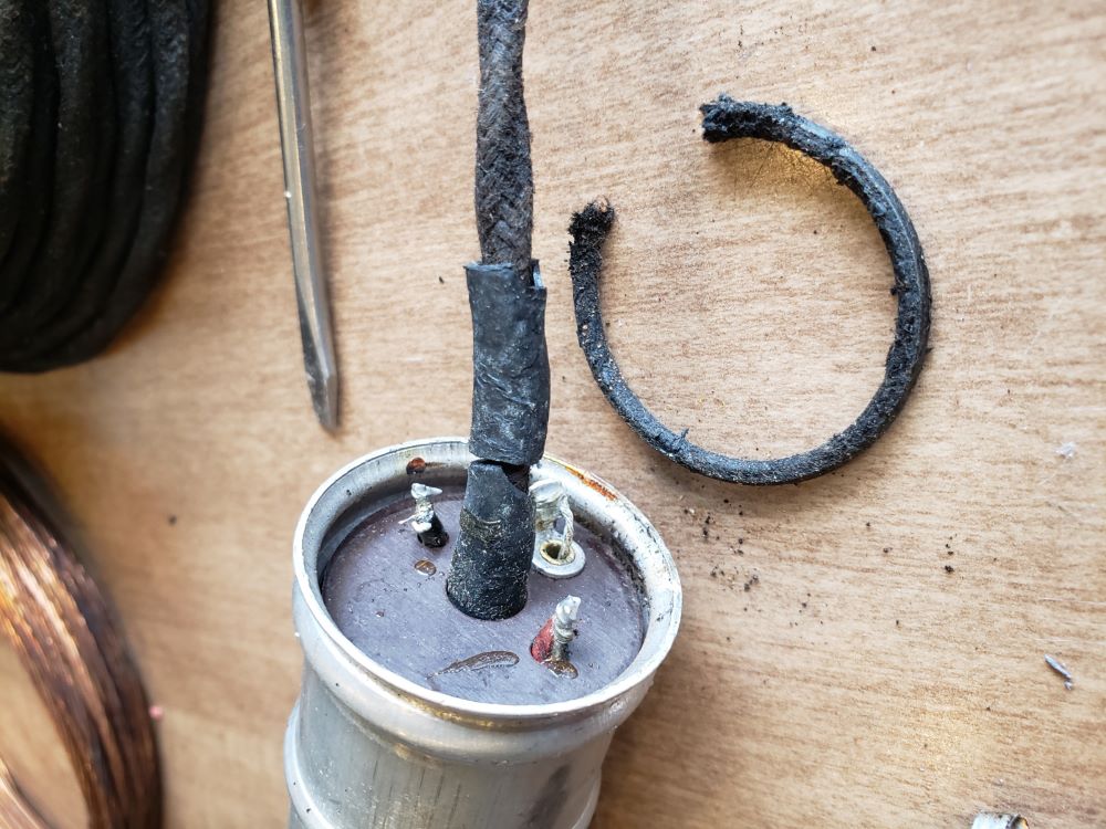
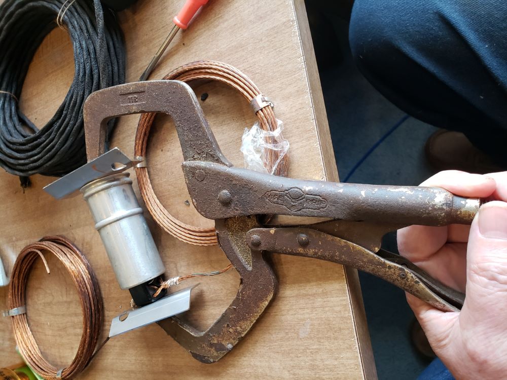
I tried unraveling the soldered antenna leg connections, but wanted to get this done before Christmas, so I snipped them off.
The legs can be reattached, loosing about 4" from each side.
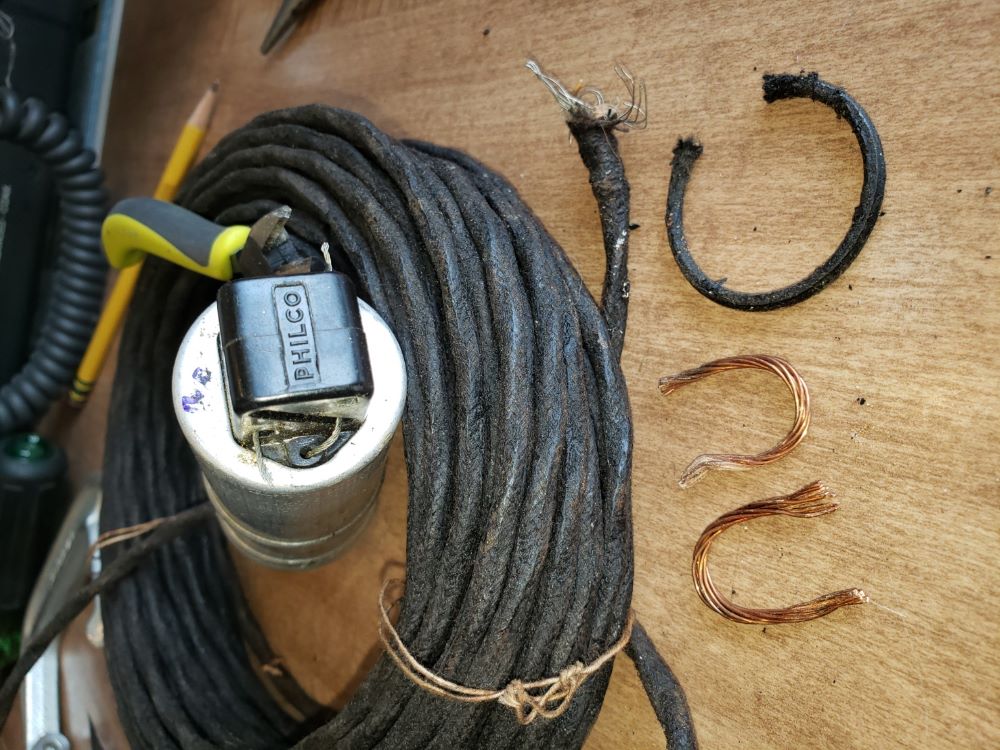
Surprise Surprise! There's tar under that paper!
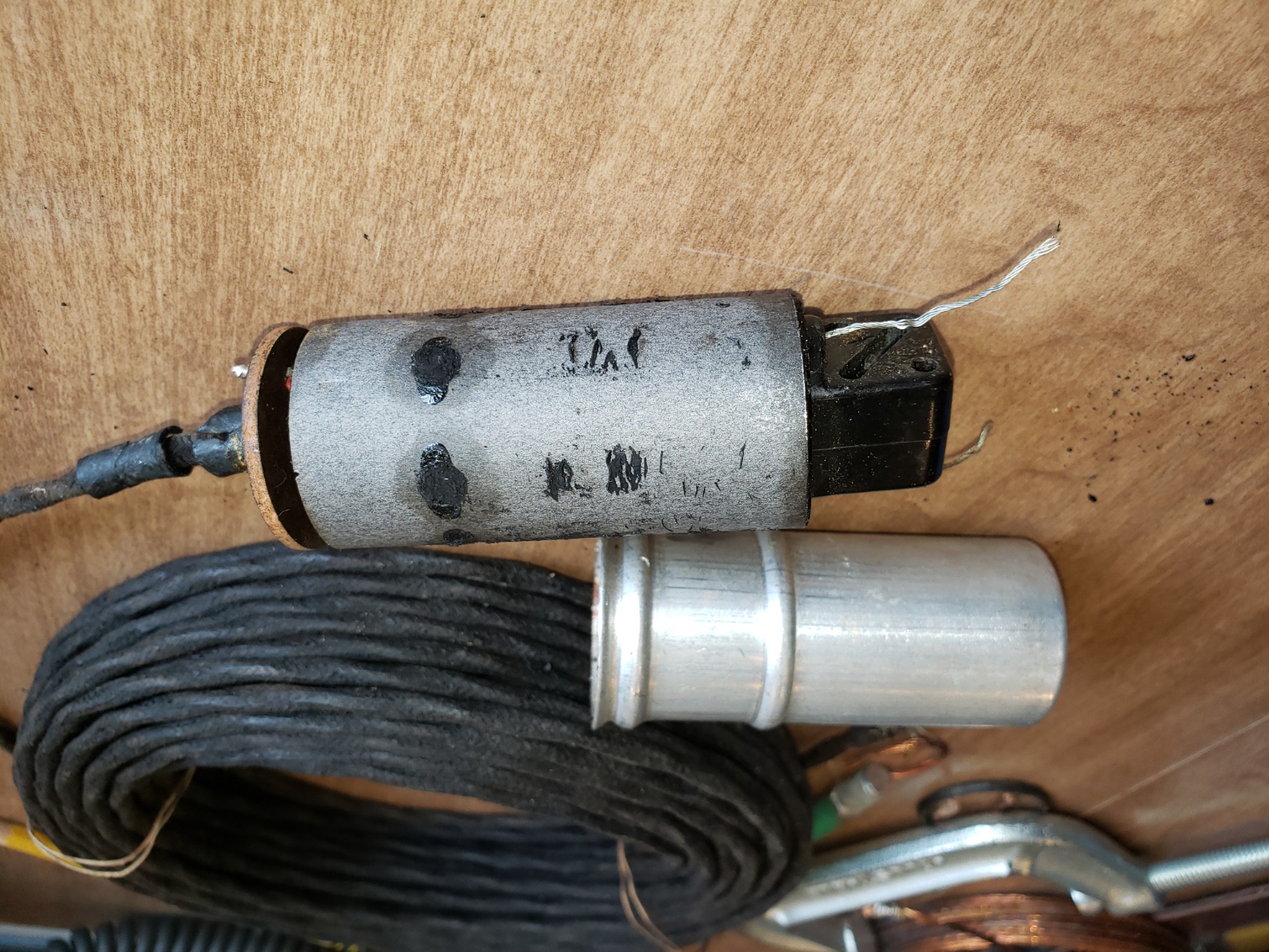
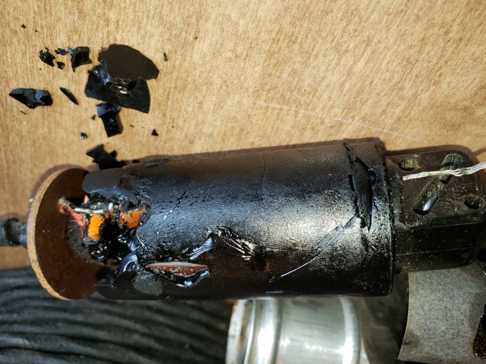
Chipping away, we find 1 resister and 5 capacitors surrounding what might be 2 coils wrapped on the same form
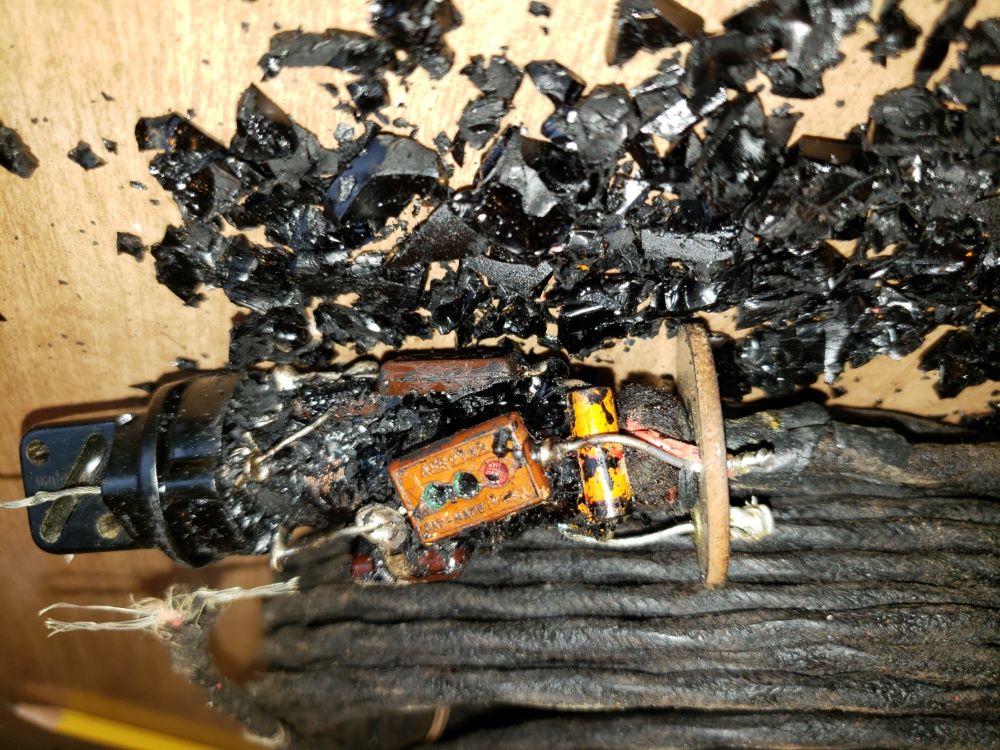
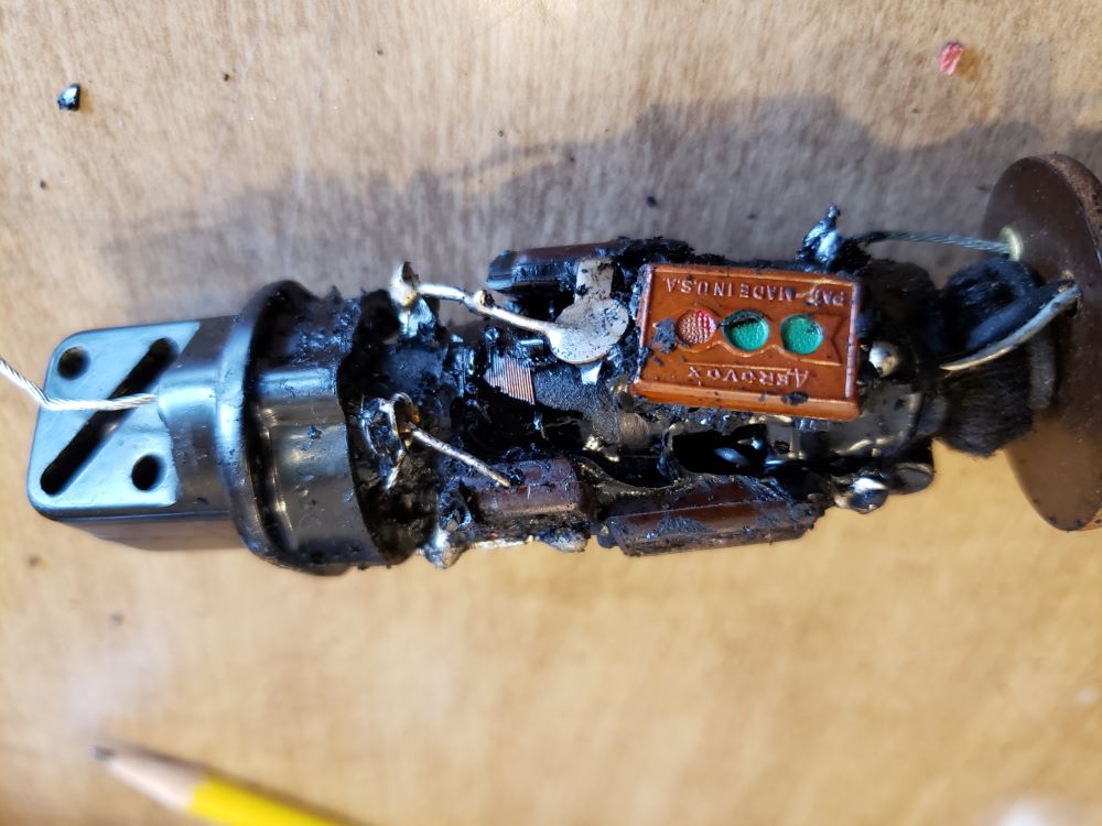
I would like to, at this time thank the OP RGK20m3 for getting me into this mess, see now what you have done! 
Now that the legs (ant wires) are removed, I check with the ohm meter Red 1 to Leg 1, and I get 15Meg ohm sinking to about 5Meg ohm which means the capacitors are charging. This holds true for Red 1 to Leg 2, Black 1 to Leg 1, and Black 1 to Leg 2.
And now I realize that I made a mistake on my diagram, the reference to either Leg should have been Meg ohms, not "ohms". I need a digital multi-meter with large font! Can I go back and fix that?
Next up: mapping out the circuit
Posts: 62
Threads: 5
Joined: Apr 2021
City: CLARKSTON
State, Province, Country: MI
Education can never have too high a price.
Posts: 103
Threads: 13
Joined: May 2020
City: Clemmons
State, Province, Country: NC
Would these baluns survive the first lightning strike?
Posts: 337
Threads: 13
Joined: Apr 2019
City: Greenwood
State, Province, Country: Delaware
radio1,
what I'm seeing so far is that it's not a Balun (Balanced to Unbalanced), as the lead-in is twisted wire and the antenna is a dipole that MAY be fed slightly off center. There seems to be a fixed tuning circuit for each leg, but it's going to take me a while to pick this tar-baby apart. The tuning coils are made from the same stuff the RF and IF coils are made of, so they break easy!
-Simon
Yes, I think lightning would take this out quickly.
Posts: 13,776
Threads: 580
Joined: Sep 2005
City: Ferdinand
State, Province, Country: Indiana
Thank you for doing this, Simon. I'm sure a lot of us here are looking forward to learning exactly how these Philco High Efficiency Antennas were designed - if they can be replicated today - and if they are worth replicating.
--
Ron Ramirez
Ferdinand IN
Posts: 337
Threads: 13
Joined: Apr 2019
City: Greenwood
State, Province, Country: Delaware
Not a problem Ron;
I wish I could just stick it in an oven, but don't think that's practical.
Always wanted to be a paleontologist anyway....
-Simon
Users browsing this thread: 1 Guest(s)
|
|
Recent Posts
|
|
1949 Motorola 5A9M
|
| This would be the second portable in the "other radios" forum where I have a similar one in my collection. I h...Arran — 12:41 AM |
|
Looking for any info: 1977 Ford-Philco Console Hi-Fi Turntable and Radio
|
| Hi PittsburgTost.
The record changer looks like a Garrard or BSR (Likely Garrard). The spindles just pull out and pu...MrFixr55 — 11:57 PM |
|
Looking for any info: 1977 Ford-Philco Console Hi-Fi Turntable and Radio
|
| Hello PittsburghToast ,
Welcome aboard and it looks like gary may have something for you !
now if I dig through my se...radiorich — 11:35 PM |
|
Model 80 Antenna Issue?
|
| You are kind of on the right path. You can touch the grid cap of the Detector/Oscillator 36 tube. I'm expecting a respon...RodB — 08:48 PM |
|
Looking for any info: 1977 Ford-Philco Console Hi-Fi Turntable and Radio
|
| Welcome to the Phorum, PittsburghToast! I found an old thread that my interest you regarding the quality and worth of P...GarySP — 08:48 PM |
|
Looking for any info: 1977 Ford-Philco Console Hi-Fi Turntable and Radio
|
| Welcome to the Phorum!
:wave:
We do not have anything on that unit in our digital library. There is a Sam's Photof...klondike98 — 08:47 PM |
|
Model 80 Antenna Issue?
|
|
I’ve replaced all the caps and resistors and the radio is working but minimal volume unless I put my hand near the re...Hamilton — 08:24 PM |
|
Looking for any info: 1977 Ford-Philco Console Hi-Fi Turntable and Radio
|
| Hi there! this is my first time posting. I recently picked up this Ford-Philco Console record player and radio at a yard...PittsburghToast — 07:28 PM |
|
philco predicta
|
| I found that where I have the 140v B+ there is 50v and the tuner receives 235v through the orange cablecgl18 — 04:14 PM |
|
Philco 91 code 221
|
| Chassis grounds thru rivets is another good place to look. Oh and the stator screws on the tuning cap where the leads at...Radioroslyn — 08:11 AM |
|
Who's Online
|
There are currently 372 online users. [Complete List]
» 1 Member(s) | 371 Guest(s)
|
|
|

|
 
|


![[-] [-]](https://philcoradio.com/phorum/images/bootbb/collapse.png)


