Posts: 16,533
Threads: 573
Joined: Oct 2011
City: Jackson
State, Province, Country: NJ
Well, I am not sure what I should've called that.
The radio has obviously been tended to by someone, and even the backelites have been restuffed.
I am still seeing things that are not exactly to my standards by nevertheless it could be a good job done by someone. Itr's just I do not leave 1940-s 1950-s electrolytics Sprague Atom in and then turn a radio on without replacing them.
Plus it seems the tin can has not beed redone but bypassed. Which is electrically speaking is just fine. The speaker cord has been made well and the splicing inside the chassis is also done well, not with some unsighty black tape but a good grade thick heatshrink tunig.
So, here are some pics.
The chassis
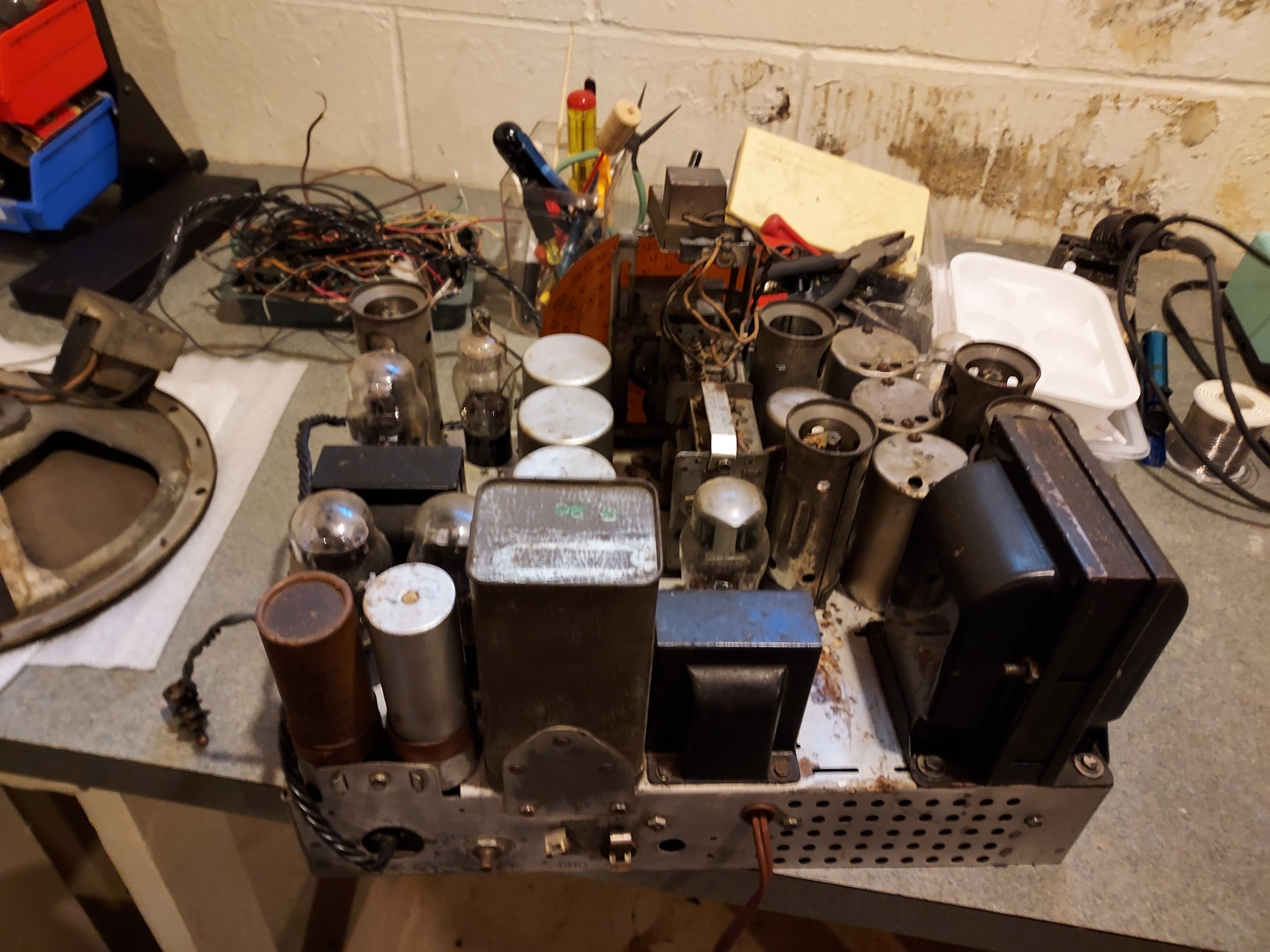
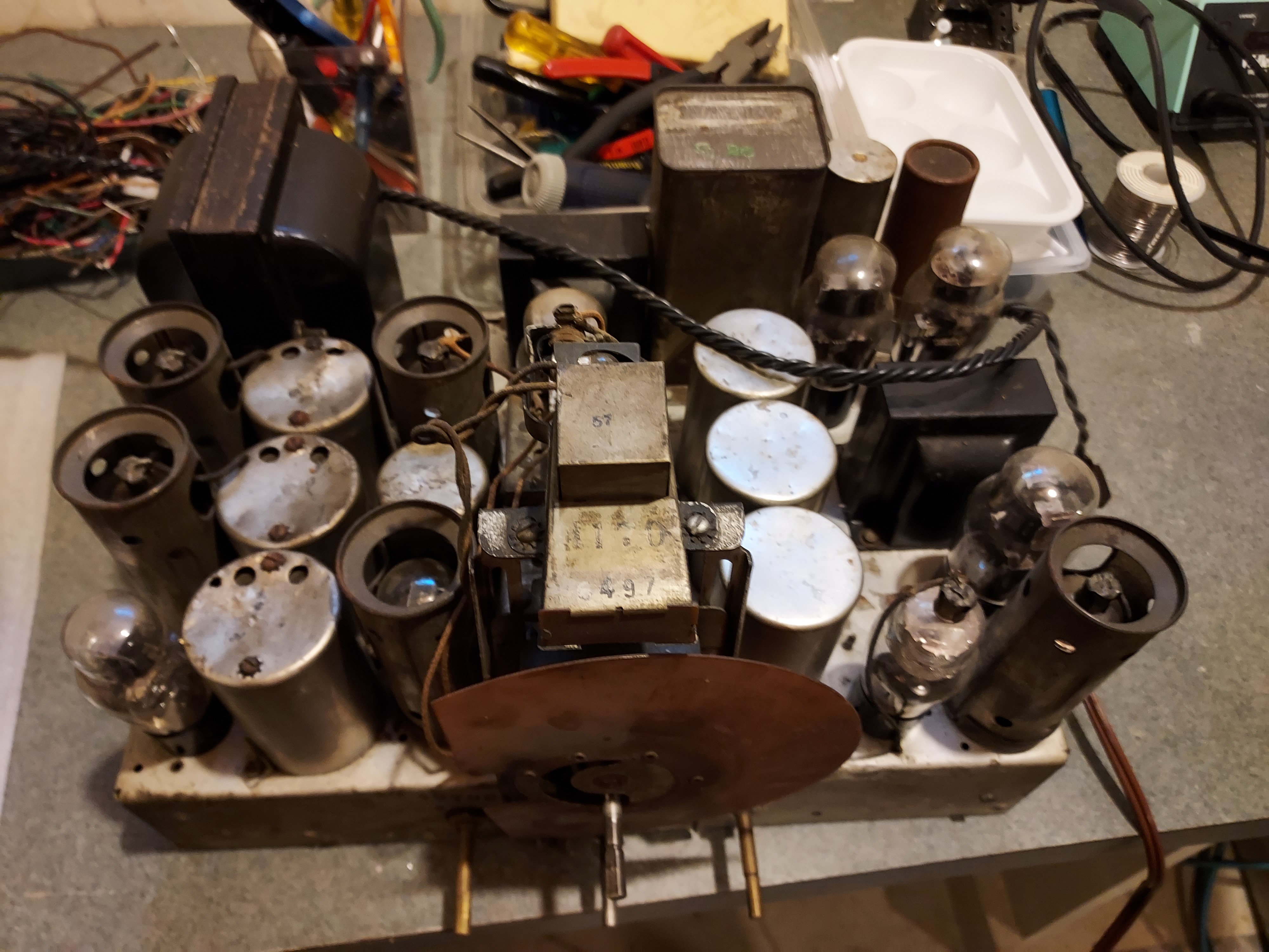
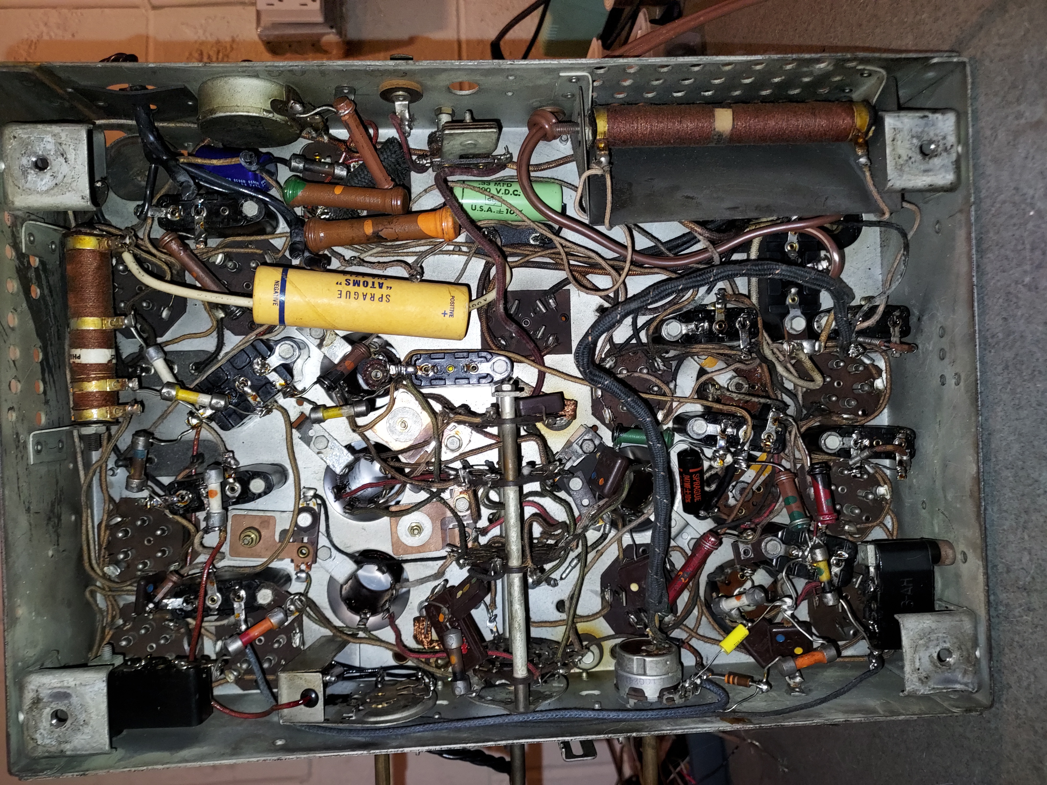
The restuffing is done with various type caps
Yellow tubular
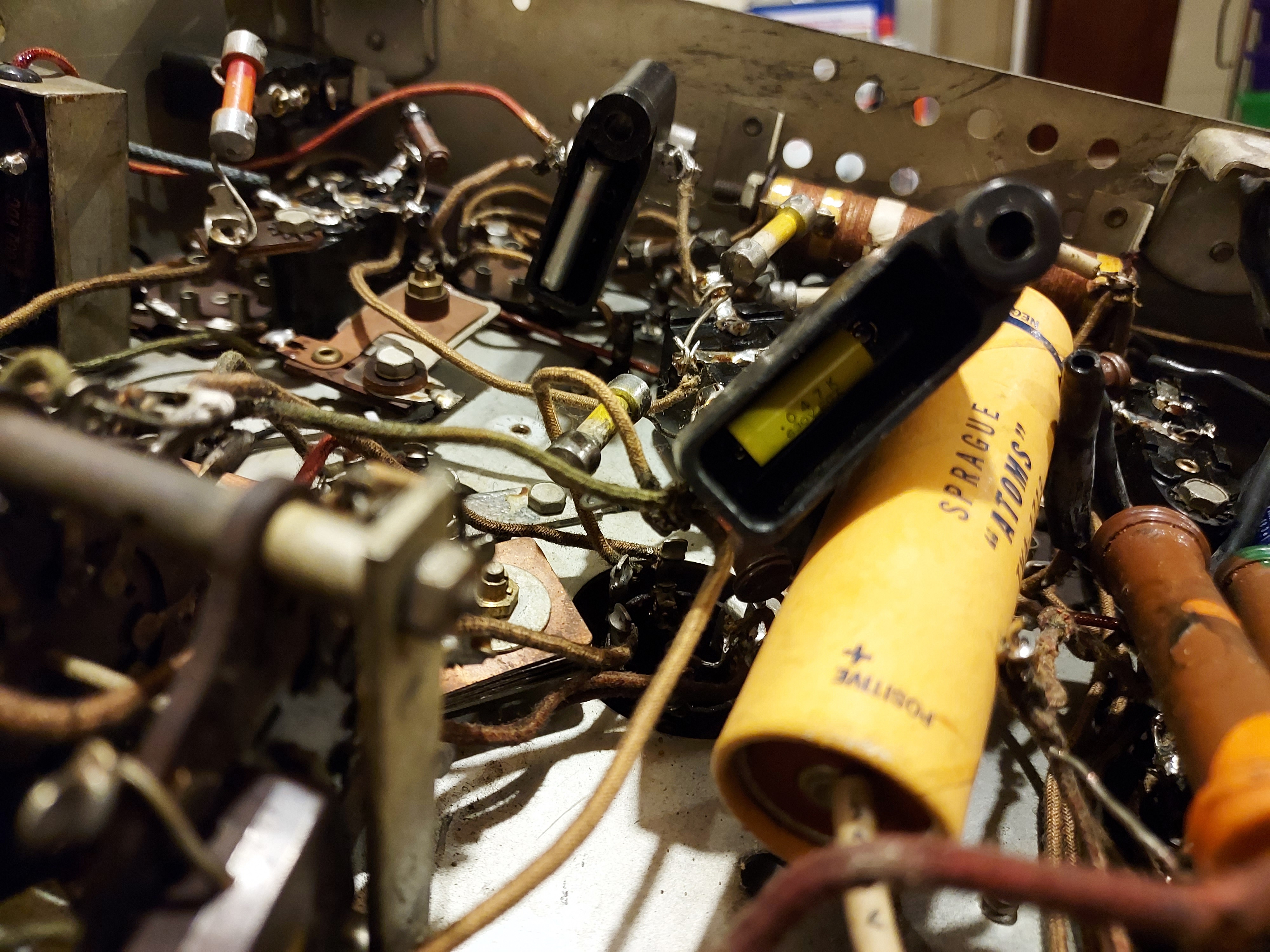
And some film type I do not use.
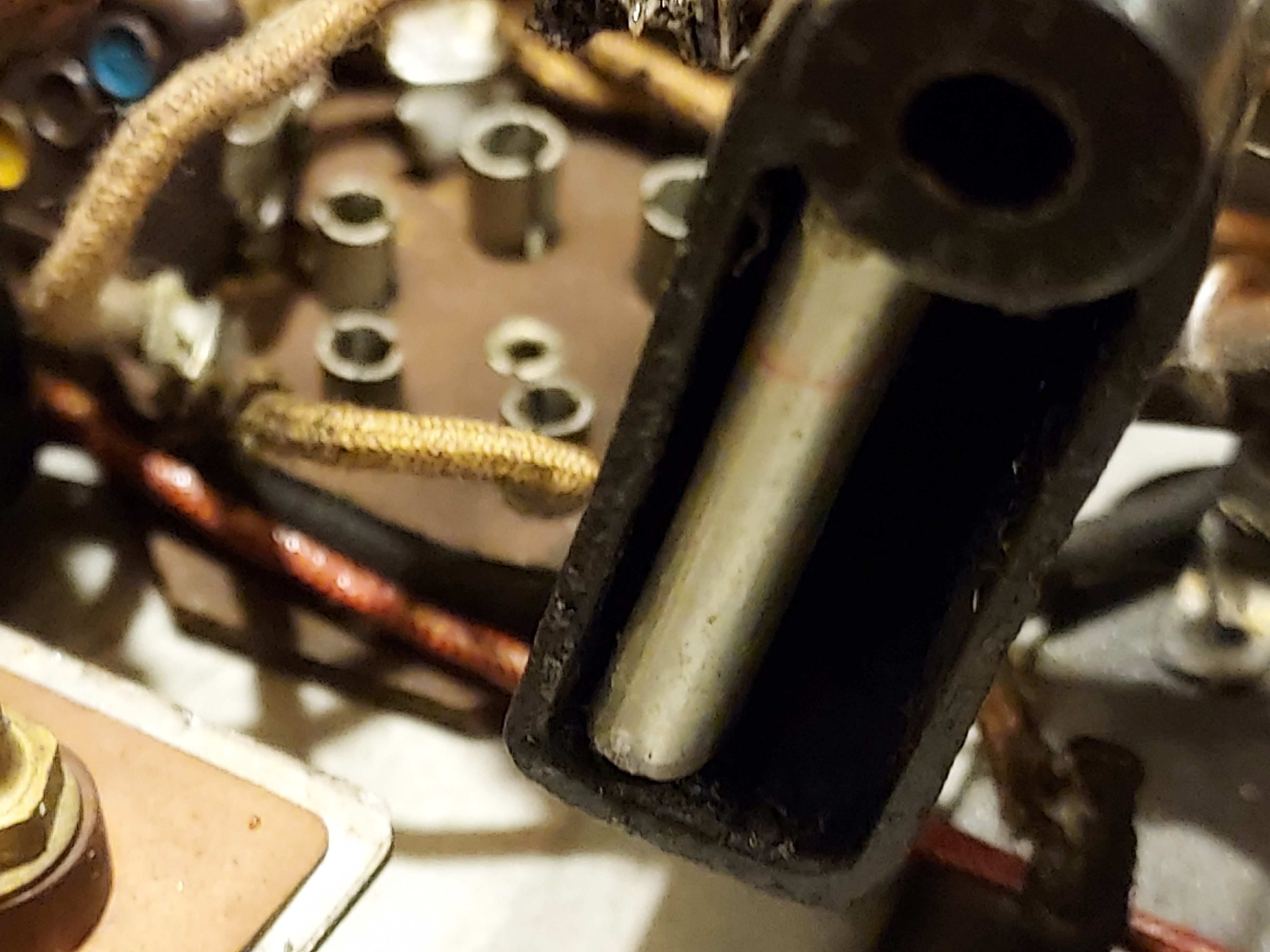
Why not? Well, the pins seem to protrude through the body. You could see a lighter spec (could not focus) at the lower end of the cap. It is the pin going through. Has it been any closer to the chassis (the blocks are raised on that cylindrical bushing), this would touch the chassis. I have not looked what cap it is and what voltage is there on taht pin, though I think it is likely OK, so I will check the value and probably leave it be if it is what it should be.
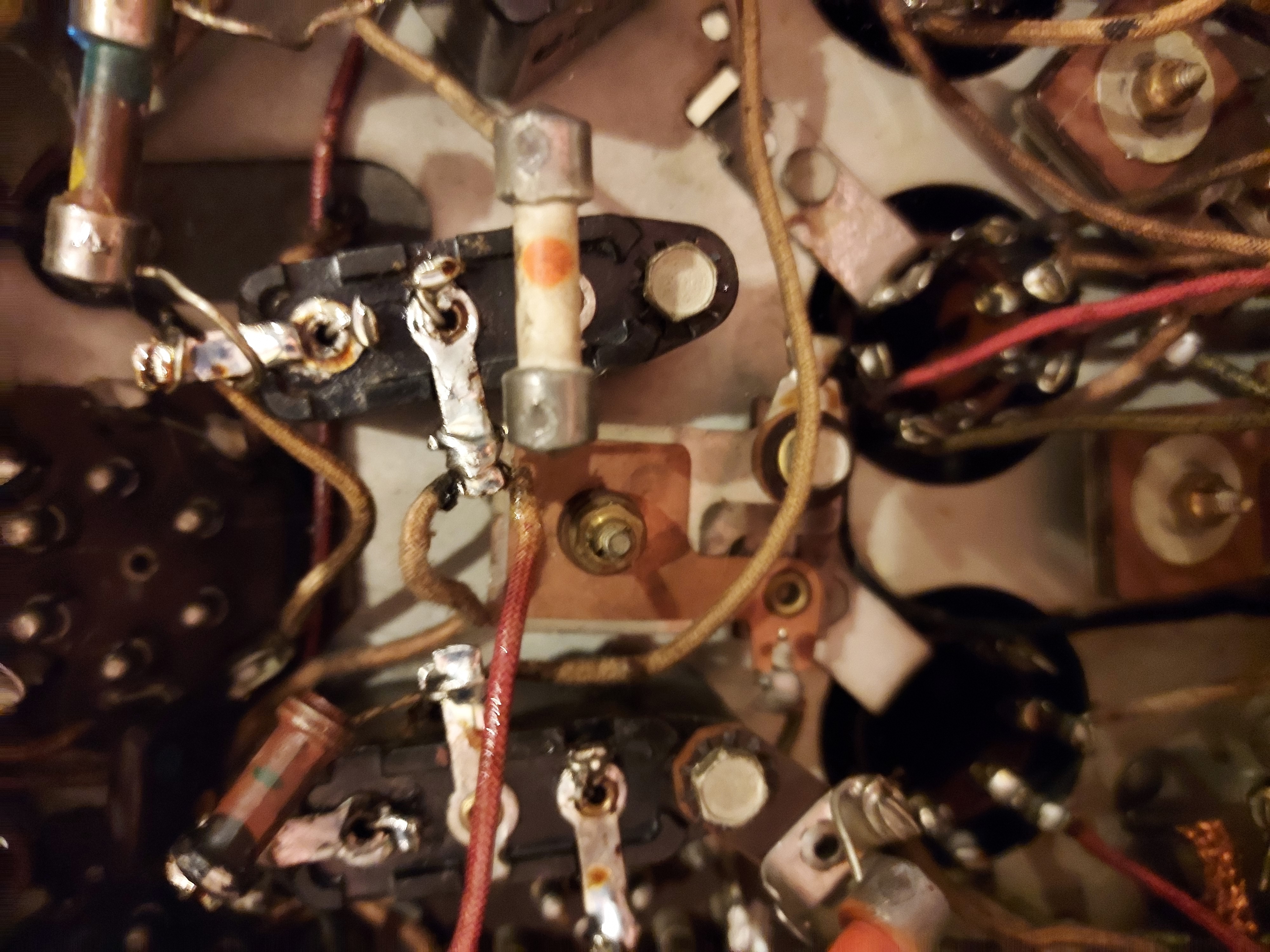
Overall this is how a fragment of the job looks, a close-up.
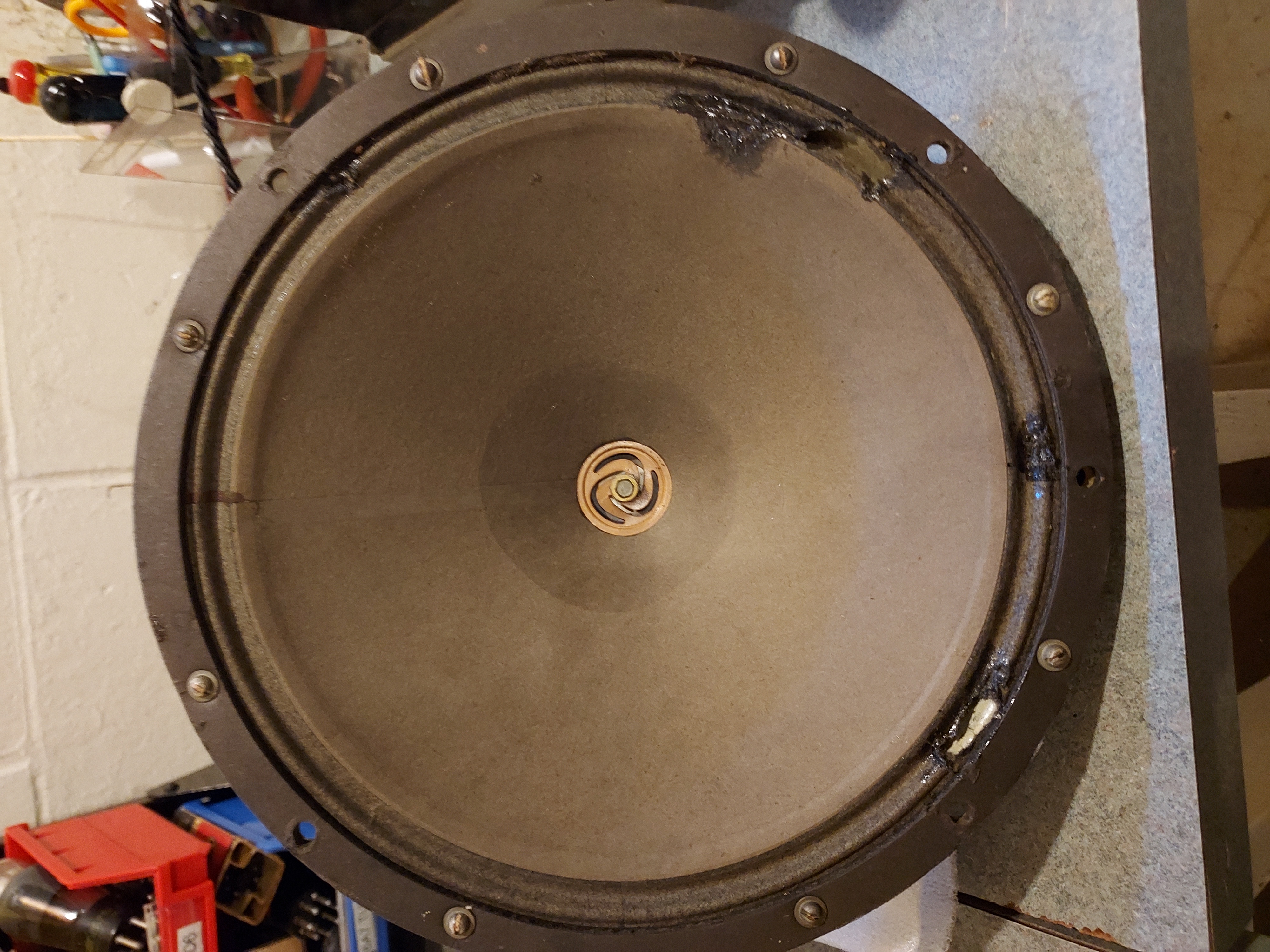
The speaker has things to be considered. Two larger holes, on the rippled part, that have been covered with what is probably a rubber cement to keep the edges from further rotting. It actually might play OK. I will think if i need to patch them or leave them, or even re-cone.
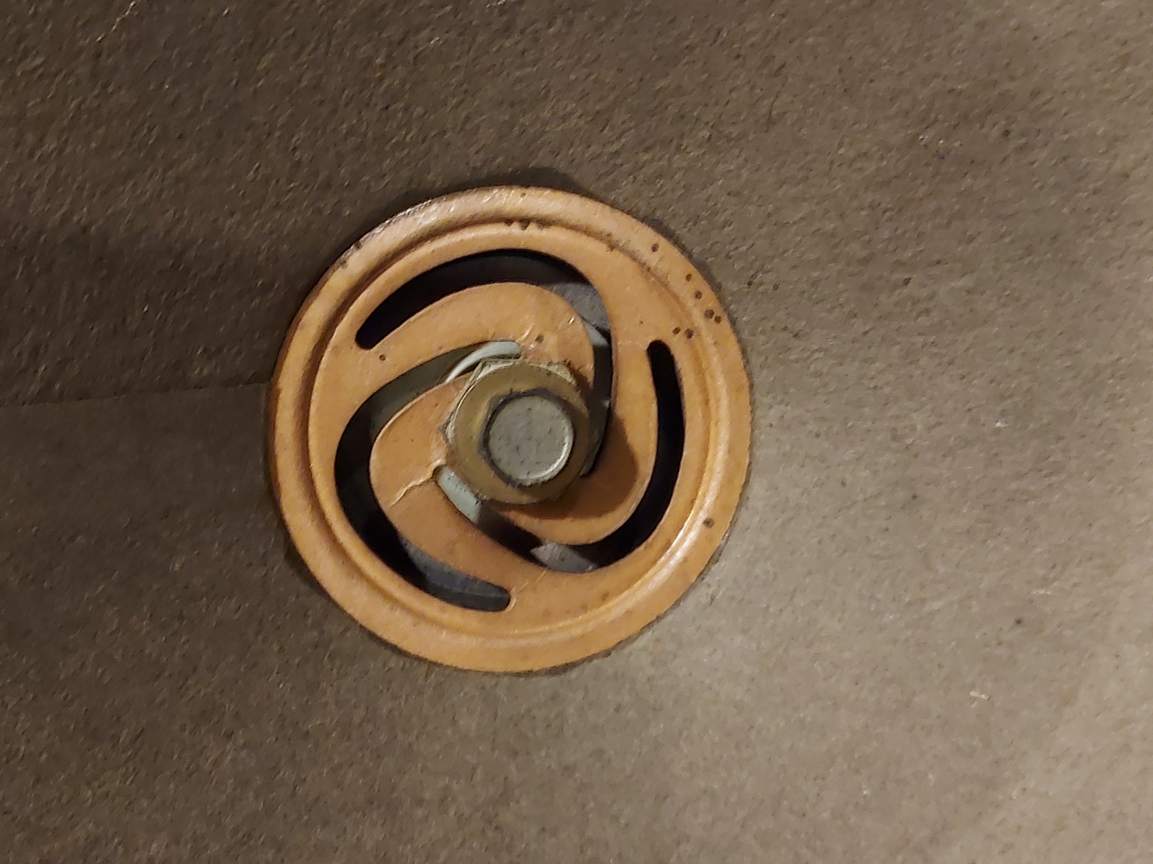
Speaking of the recone, the previous problem alone might've not make me think of it, but the spider has cracks. They are not break-offs with full separation, but cracks nevertheless, so if I play that, I am not sure how long this would hold, or if it is affecting the sound already.
I have also checked the tubes, all are excellent except one 76 tube, which is less than 50%. Luckily I have a couple, both are very strong.
This is my 4th Philco 16. I have 16B cathedral, 16B shouldered (bought from Ron), 16X I have recently finished (Kirk's forced gift) and now this one, a peaked 16B, also bought when Kirk made me an offer I could not refuse.
Later.
People who do not drink, do not smoke, do not eat red meat will one day feel really stupid lying there and dying from nothing.
Posts: 7,303
Threads: 269
Joined: Dec 2009
City: Roslyn Pa
That Sprague "atoms" cap reminds me of some caps that were around when I was a kid in the 60's. It's a little hard to tell from the pic but the ones that were about 1 1/2" x 4" long were 100mfd at 450v. A little over kill for your 16B.
On the code 121's I've been putting Philco spkr plugs/sockets on them. It just make life easier to move it around. On the tombstone (1934) installing the spkr back into the cabinet is little precarious. Having the chassis half out and aligning the edge of the spkr into to cove at the peak cabinet. As the hold down screws are sliding out of the front. It can be a little frustrating.
They are fun sets to work on... Sometimes...
When my pals were reading comic books
I was down in the basement in my dad's
workshop. Perusing his Sam's Photofoacts
Vol 1-50 admiring the old set and trying to
figure out what all those squiggly meant.
Circa 1966
Now I think I've got!
Terry
Posts: 16,533
Threads: 573
Joined: Oct 2011
City: Jackson
State, Province, Country: NJ
OK, I have the Volume pot from Mark now.
Here's a question: as I said, the volume pot was wrong, and the circuit was a tad different from the original due to the fact that the repairman was trying to work around the pot that had no tap. The repair was done in 40w or possibly even 50s, as three 0.0033uF Black Beauty caps we used to stuff the tone control, and anothe BB plus Atom caps were used in the chassis.
Now, the chassis has the AVC pot, so I take it, it is likely code 121.
Am I to understand the schematic we have in the Library for the radio has the latest service updates, related to the volume/tone ctl, incorporated into it? It looks like it. But I want to make sure.
People who do not drink, do not smoke, do not eat red meat will one day feel really stupid lying there and dying from nothing.
Posts: 5,182
Threads: 276
Joined: Nov 2012
City: Wilsonville
State, Province, Country: OR
Mike,
I had an 84B that had a speaker spider that had failed completely. I took a shot at repairing it and you can see that in my thread for that radio. It sounded OK after the repair, although I don't really know how well it would last if you were playing the radio all the time. Its not a radio I play regularly.
Posts: 7,303
Threads: 269
Joined: Dec 2009
City: Roslyn Pa
There does seem to be 2 different tone networks used on the code 121 chassis. They don't use the same rotatory switch. It would be much easier to stick with circuit it has rather to convert it to the other. https://philcoradio.com/library/download...%20165.pdf & https://philcoradio.com/library/download...l.%201.pdf All 3 of the code 121's I have are like yours w/the three .003's.
When my pals were reading comic books
I was down in the basement in my dad's
workshop. Perusing his Sam's Photofoacts
Vol 1-50 admiring the old set and trying to
figure out what all those squiggly meant.
Circa 1966
Now I think I've got!
Terry
Posts: 16,533
Threads: 573
Joined: Oct 2011
City: Jackson
State, Province, Country: NJ
Bob,
Thanks. Not a bad idea.
Terry,
I am not about to convert anything, but the circuit relied on a wrong resistor so they altered it so it is not one of anything you could find. I told you before in Kutztown.
They converted from an original 121 circuit (where the tone CTL was from the pot's tap) to the 3x0.0033uF from the 1st Audio plate. While having to work around the no-tap pot.
Now I am leaving the 3x0.0033uF tone Ctl from the 1st Audio plate in place. I just want to re-create a correct, hopefully the last one, circuit that is in service bulletins. They already have the 330kOhm resistor in parallel with the pot through a 10nF capacitor to the top pot pin.
The PDF sch you have (not the bulletin) is the same as the sch the library has (or maybe you gave the link to it), so I think I am going to follow that one.
People who do not drink, do not smoke, do not eat red meat will one day feel really stupid lying there and dying from nothing.
Posts: 16,533
Threads: 573
Joined: Oct 2011
City: Jackson
State, Province, Country: NJ
Many things in the radio are not exactly according to the schematics, and, considering the volume/tone ctl mod, it is none of the existing versions.
I convert it to more or less the latest code 121. I am done with tone ctl/volume.
I also am weeding out non-original standalone tubulars. One last I have, a black beauty, is supposed to be a part of a dual backelite block, which in my case is single cap one.
I simply find an old cap of a proper value, of which I have a fair amount, especially the popular value of 0.047uF, and stuff it with a new cap.
Then I have the tin can block to re-do.
Many resistors are in very good shap and are within 10%, some even better, but large value (1.5M, 2M) are far gone and will have to be replaced.
As I said before, the backelite blocks have bee taken care of by the previous owner and are restuffed. I checked 2 or 3, they are correct.
People who do not drink, do not smoke, do not eat red meat will one day feel really stupid lying there and dying from nothing.
Posts: 16,533
Threads: 573
Joined: Oct 2011
City: Jackson
State, Province, Country: NJ
Someone seriously went over this radio. The tin can is rebuilt. I will check the cap values, but I think they are OK. The electrolytics were a bit too large; the Atom cap across the rectifier was 50uF which is too large.
I found a backelite block and added it to put that 0.3uF across the choke (yes, i know, the recent trend is dump it) and removed the large tubular axial cap soldered right acreoss the choke; also weir fact but the electrolytic which looks 1950-s is OK. So is that pretty old tubular across the choke.
The power divider (13/15/10K) has moved a bit so I corrected it.
I think I will rebuild the electrolytics and add one small 10uF one decoupling the GND to the Rect centertap Negative.
People who do not drink, do not smoke, do not eat red meat will one day feel really stupid lying there and dying from nothing.
Posts: 16,533
Threads: 573
Joined: Oct 2011
City: Jackson
State, Province, Country: NJ
The tin can has 4 good film caps (well, three - two are in parallel to make 1uF) and tfwo electrolytics. Those are probably from 60s or 70s. They are 5uF caps and measure 6.5 - 7uF. I replaced them with film caps.
Now I am rebuilding electrolytic caps.
The resistors are done.
People who do not drink, do not smoke, do not eat red meat will one day feel really stupid lying there and dying from nothing.
Posts: 16,533
Threads: 573
Joined: Oct 2011
City: Jackson
State, Province, Country: NJ
There are two tubular electrolytics.
One is a dual, a Philco cap, 10uF and 8uF replacement type. Surprisingly it showed 10uF and 10uF on both halves. Not an original one, I think.
The other is a Cornell cardboard shell one. I decided it looks age-appropriate.
The 10+10uF was actually used, probably as the Ground to Centertap cap. I have not found the original one that is supposed to be used for it.
So I decided `to make the dual one to be the rectifier and the filter caps; the first would be a Solen 8.2uF and the other 22uF 450V, a high ripple type so it lasts forever.
And the cardboard I made into the missing 10uF Centertap-to-GND cap.
So yesterday I started gutting the cardboard one. I remember failing a few years ago in doing so, as I could never extract the core, and in trying to break the top layer of whatever that is, a brittle potting compound, I destroyed the shell.
So this time I chipped at the top layer with a small chiesel, it was like 5/16" thick, and successfully got to the softer core. I then tried to use a corkscrew to extract it, with no success. Then I used heat and then the corkscrew, also with no success, no matter the effort.
So how did I do it, you ask? Well, I soaked the cap in mineral spirits for a day. Then I tried the corkscrew, again unsuccessfully, and then I decided to use the heat gun again, and this time the soaked and heated core came out without much effort.
So this is what you do: remove the top hard potting compoundm soak the cap in mineral spirits overnight and with some (not even much) heat use a corkscrew to gut it.
Then I quickly cleaned the interior of the remnants of that hard tar at the bottom, cleaned it with mineral spirits, and then I did what the photos below show.
The shell is gutted.
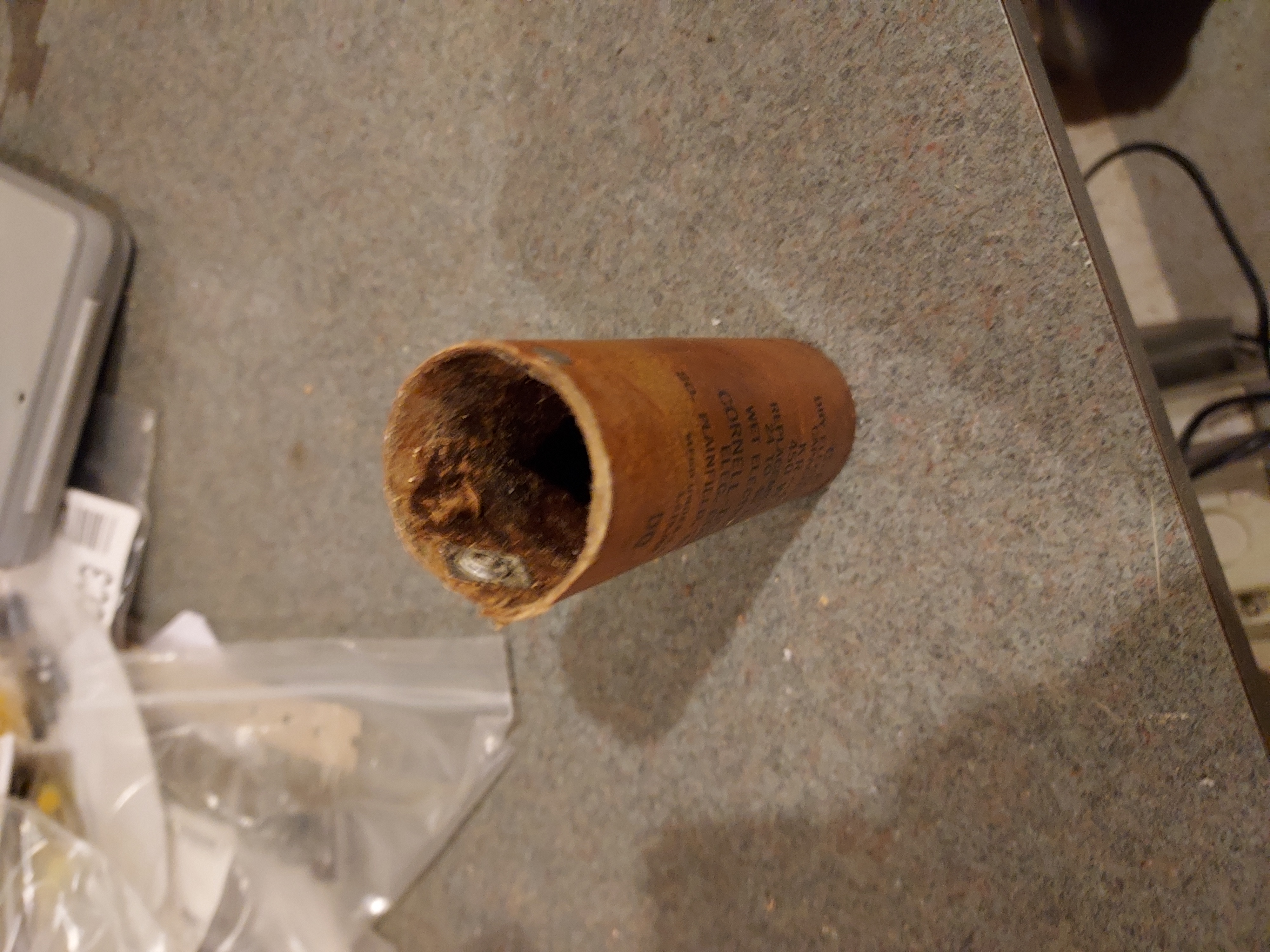
Fishpaper bottom is made and the wired cvap is inserted.
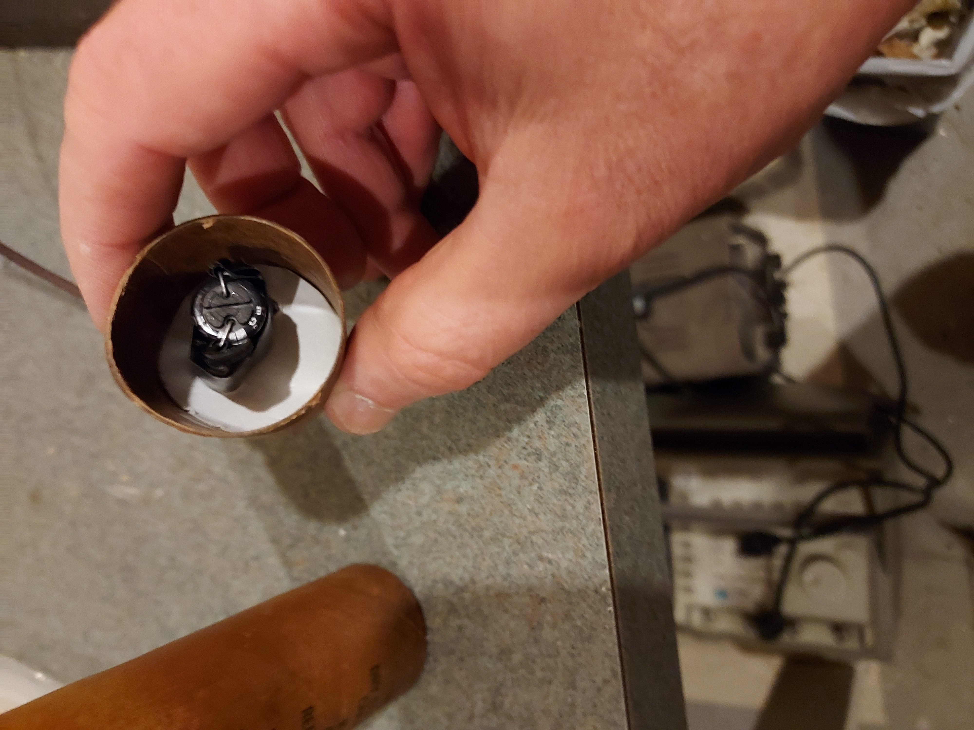
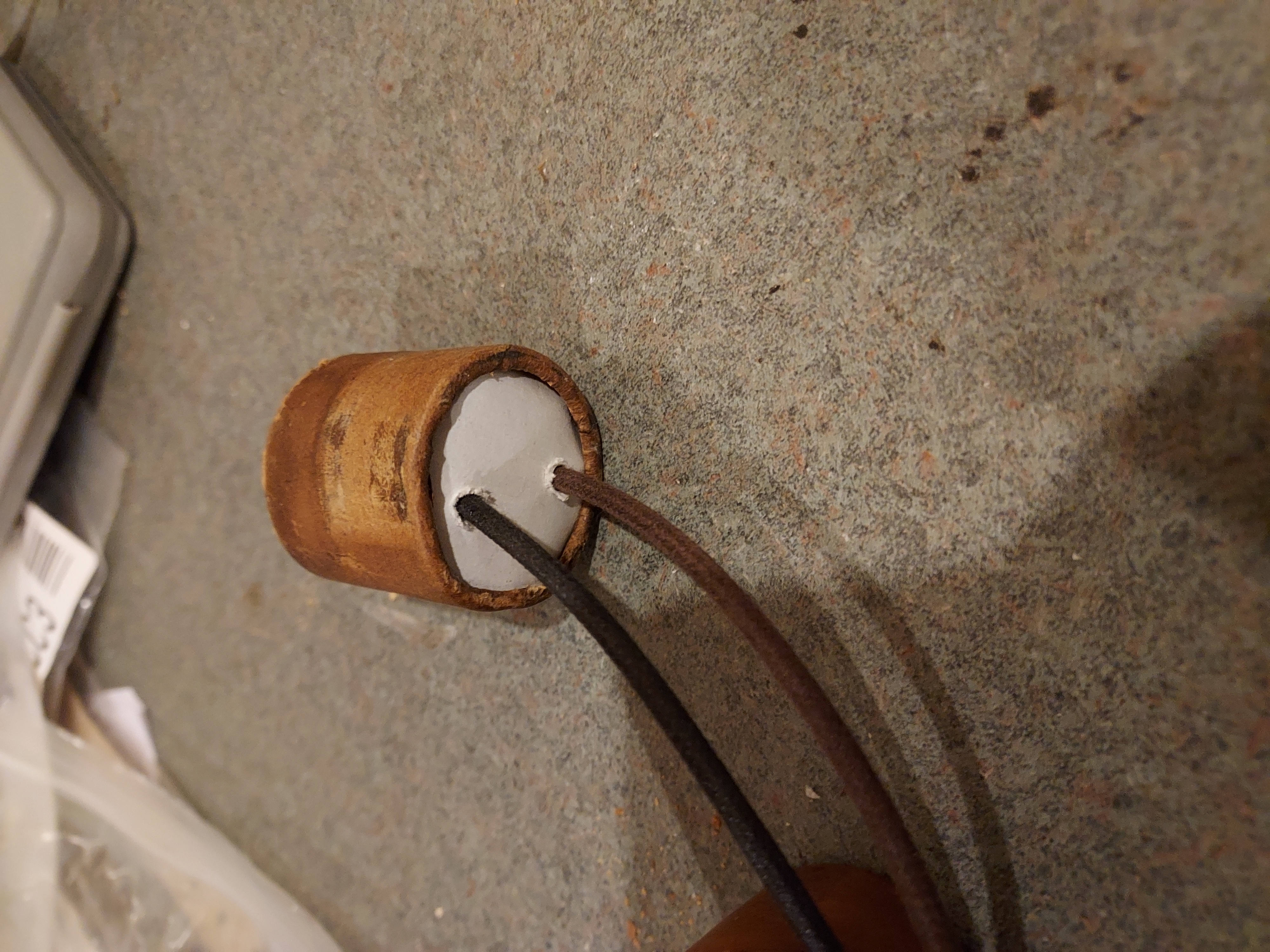
The cap's wires are potted inside and the bottom is potted outside.
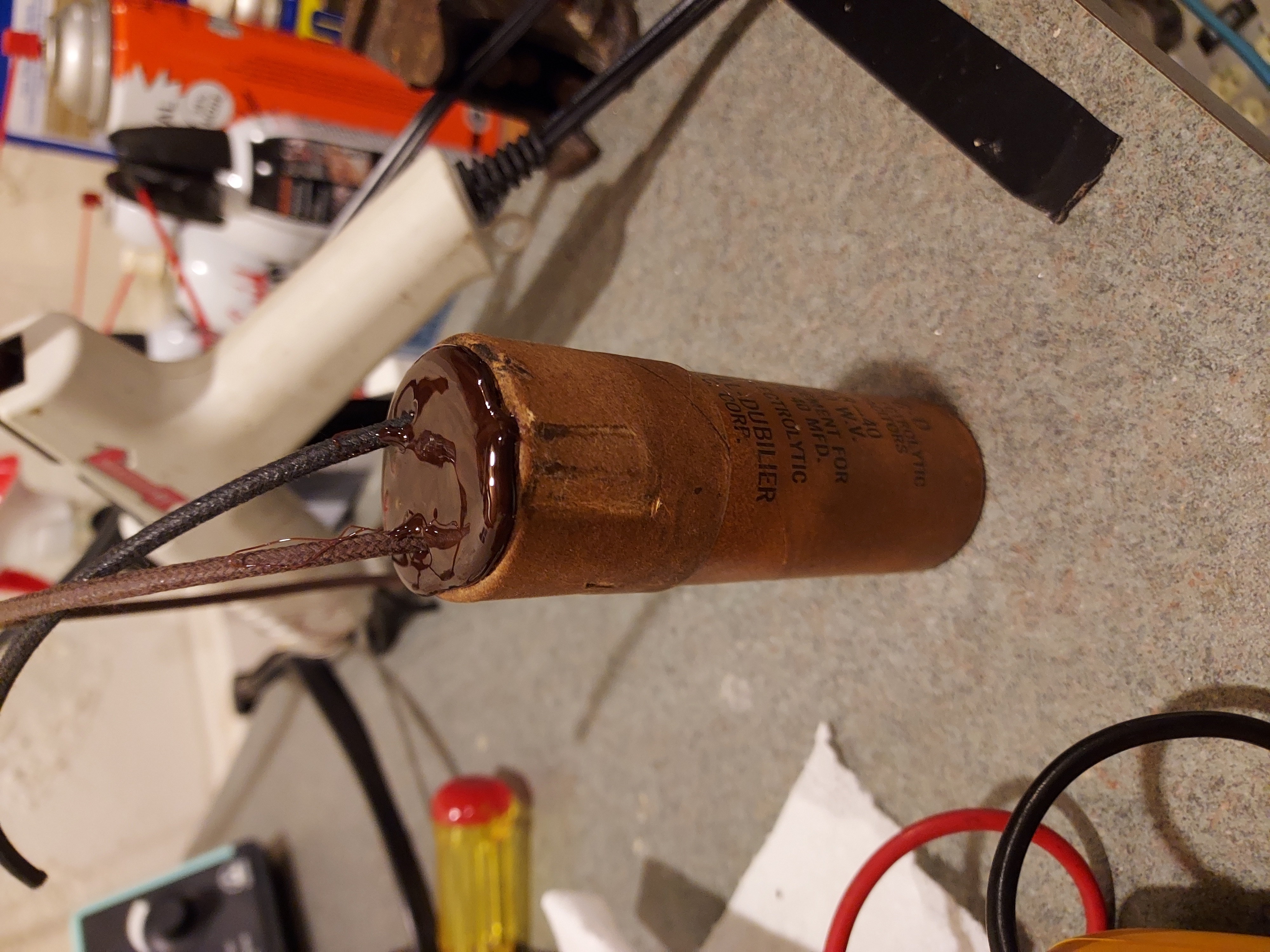
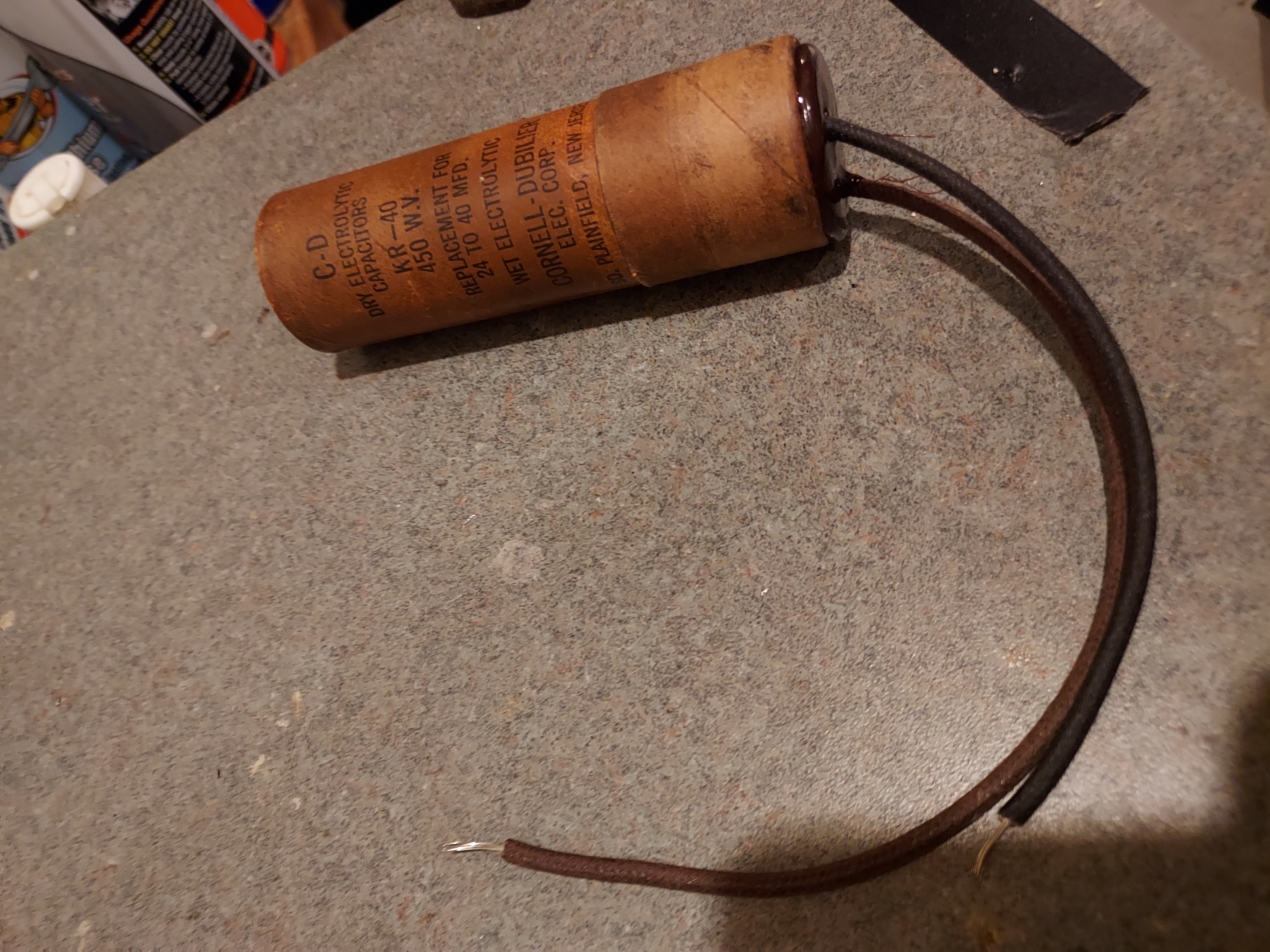
The aluminum cap's shell is meantime being soaked in vinegar to remove all salts that are left. This one gutted very easily.
People who do not drink, do not smoke, do not eat red meat will one day feel really stupid lying there and dying from nothing.
Posts: 16,533
Threads: 573
Joined: Oct 2011
City: Jackson
State, Province, Country: NJ
Then I took the aluminum cap from vinegarv bath. It clean it remarkably well. Rinse with water, dry.
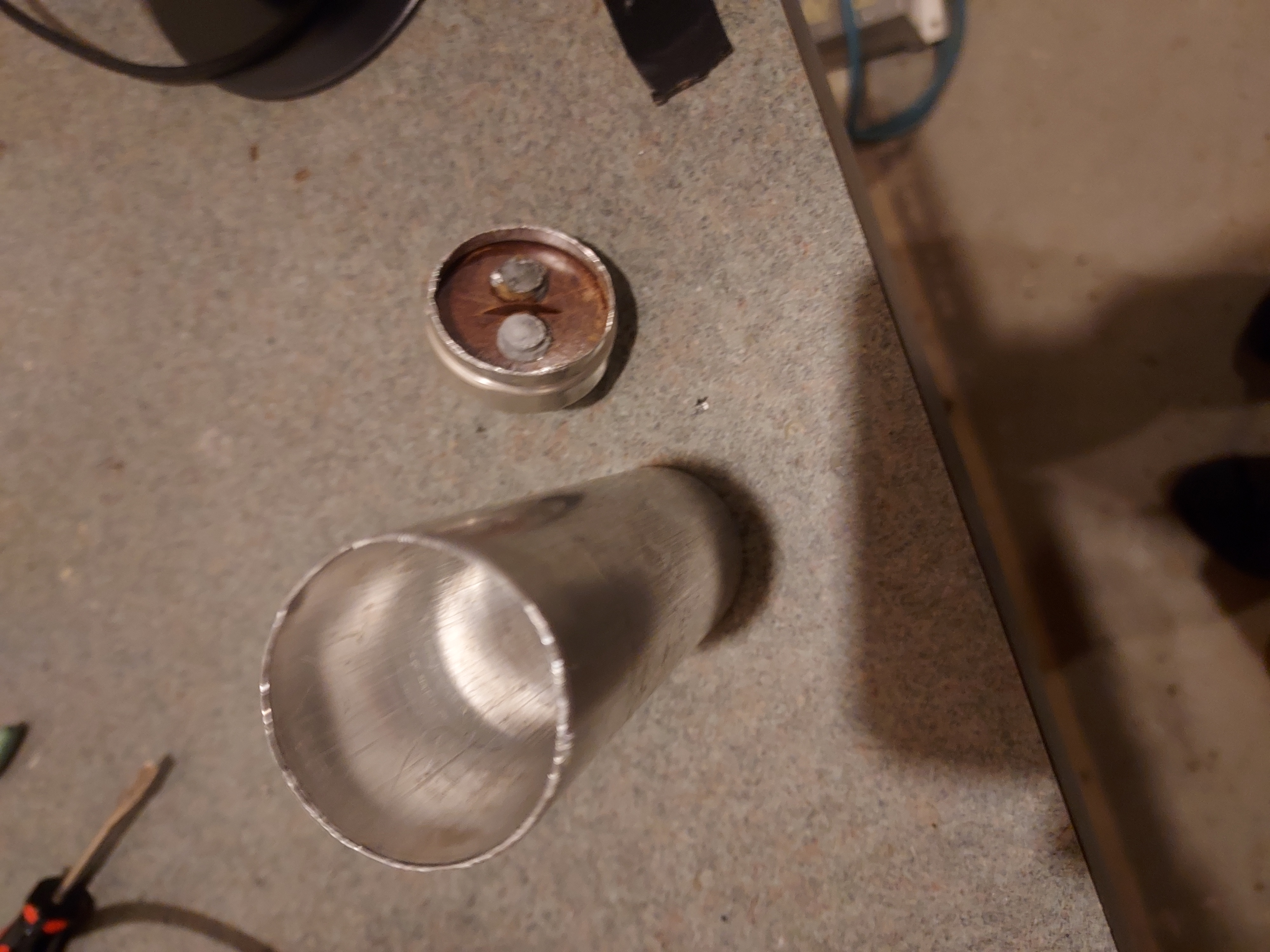
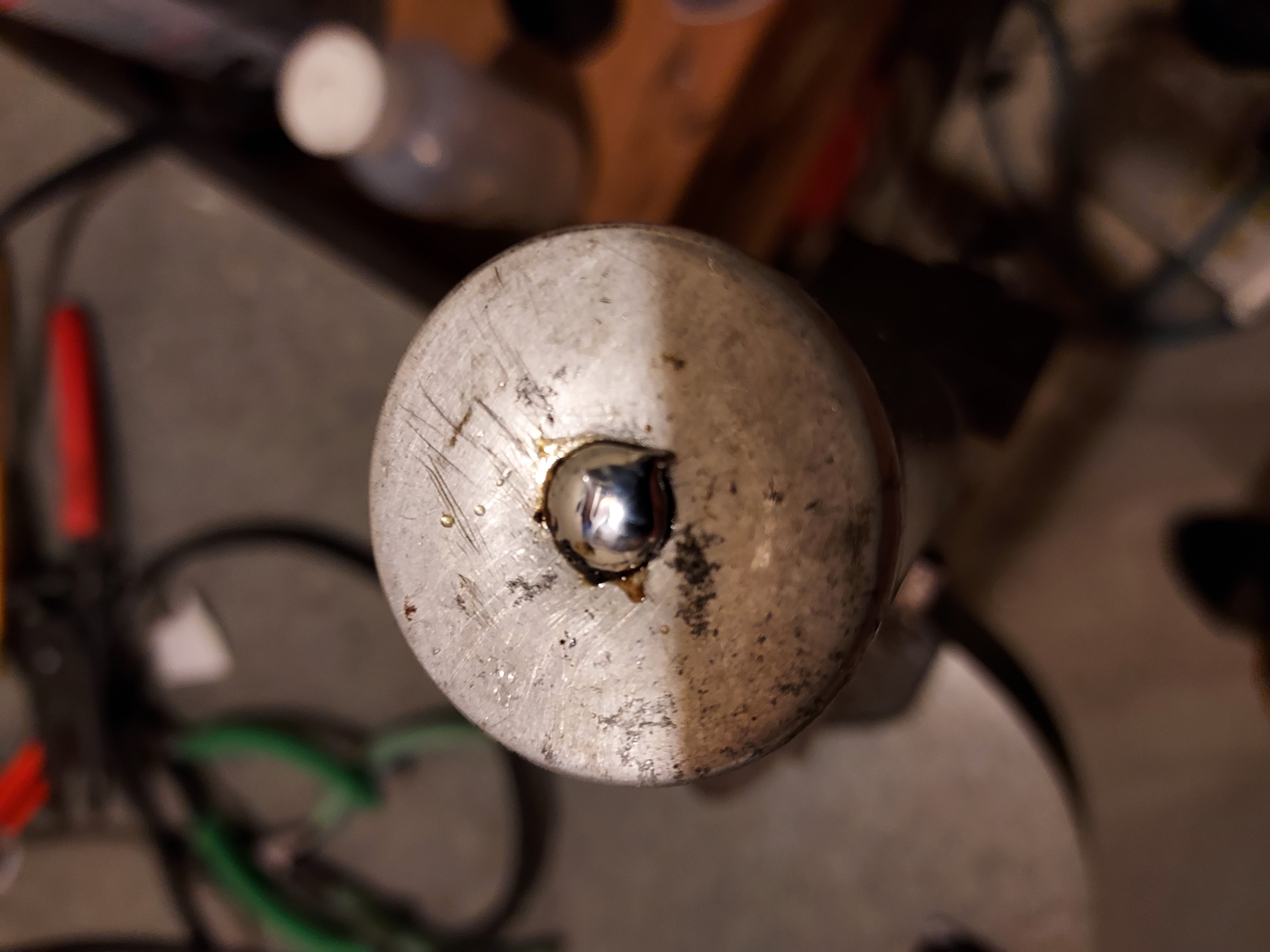
Also the top, where there was the rubber plug, is fitted with a copper rivet to accomodate the common minus wire.
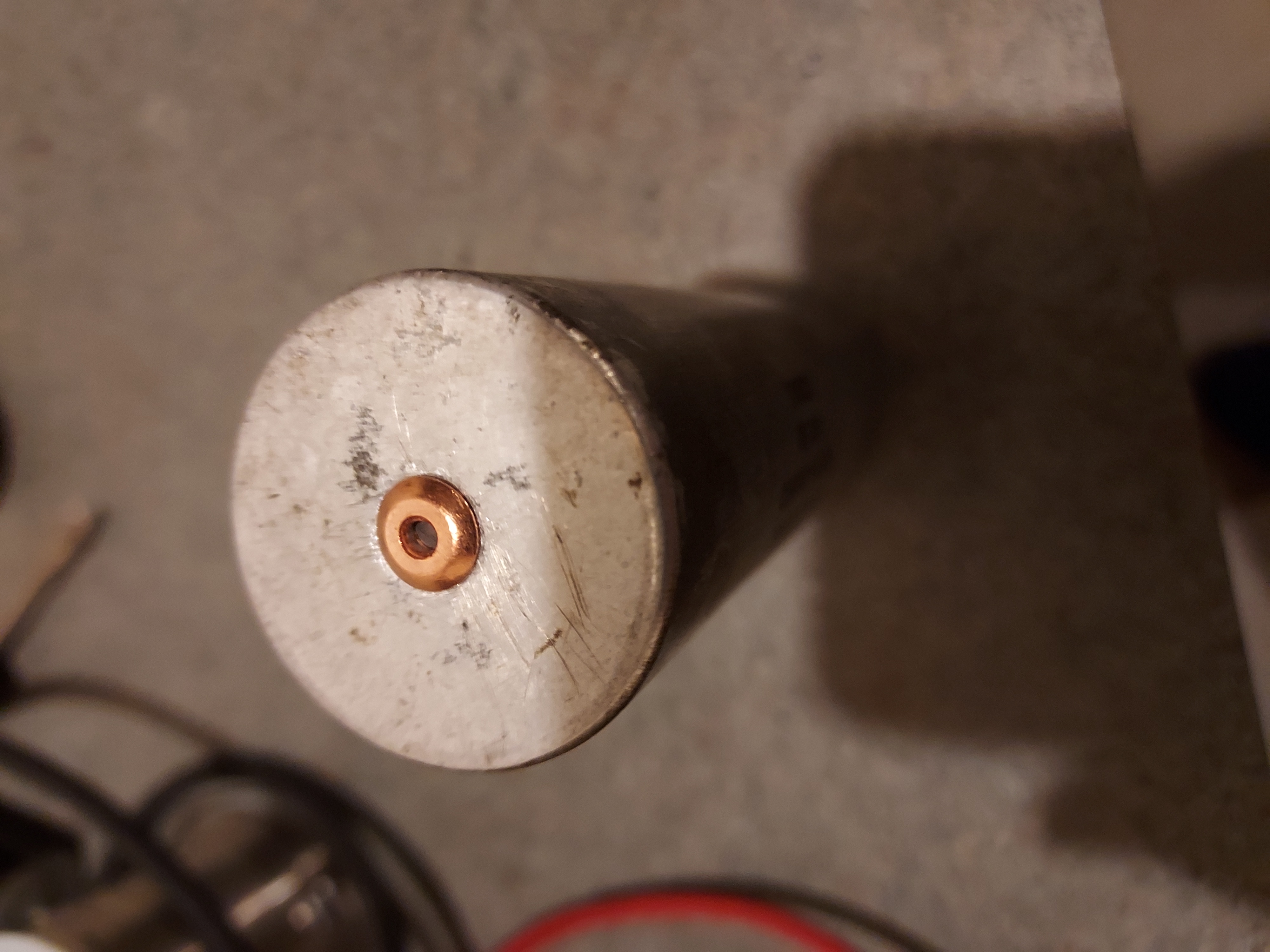
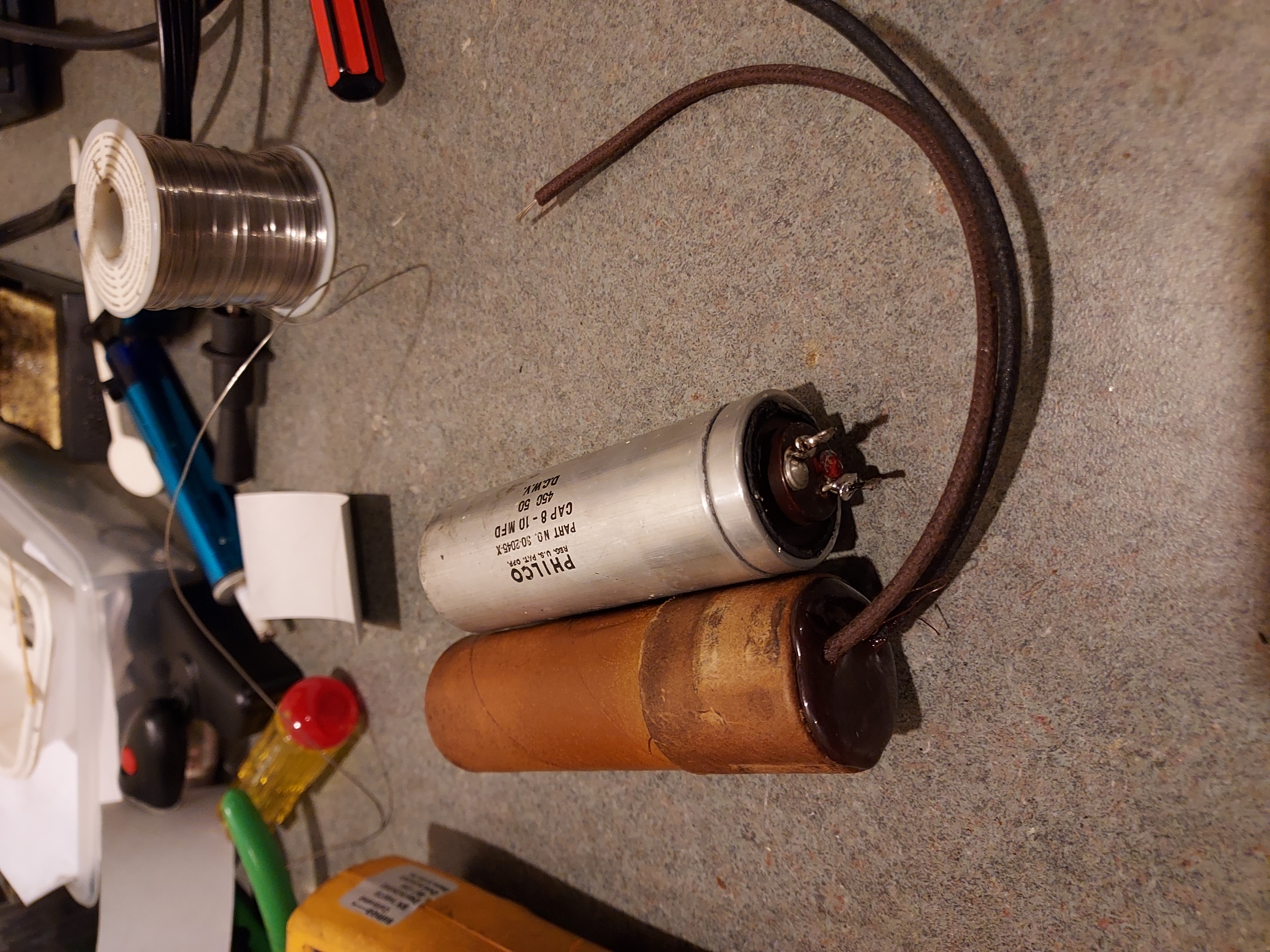
Then make the stuffing. An 8uF Solen cap with a 22uF hi-ripple 450V Panasonic cap on top. The 22uF is wrapped in fish paper so that it keeps the wires from touching close to aluminum shell etc.
The common minus is sticking up and will go through the center of the top of the can.
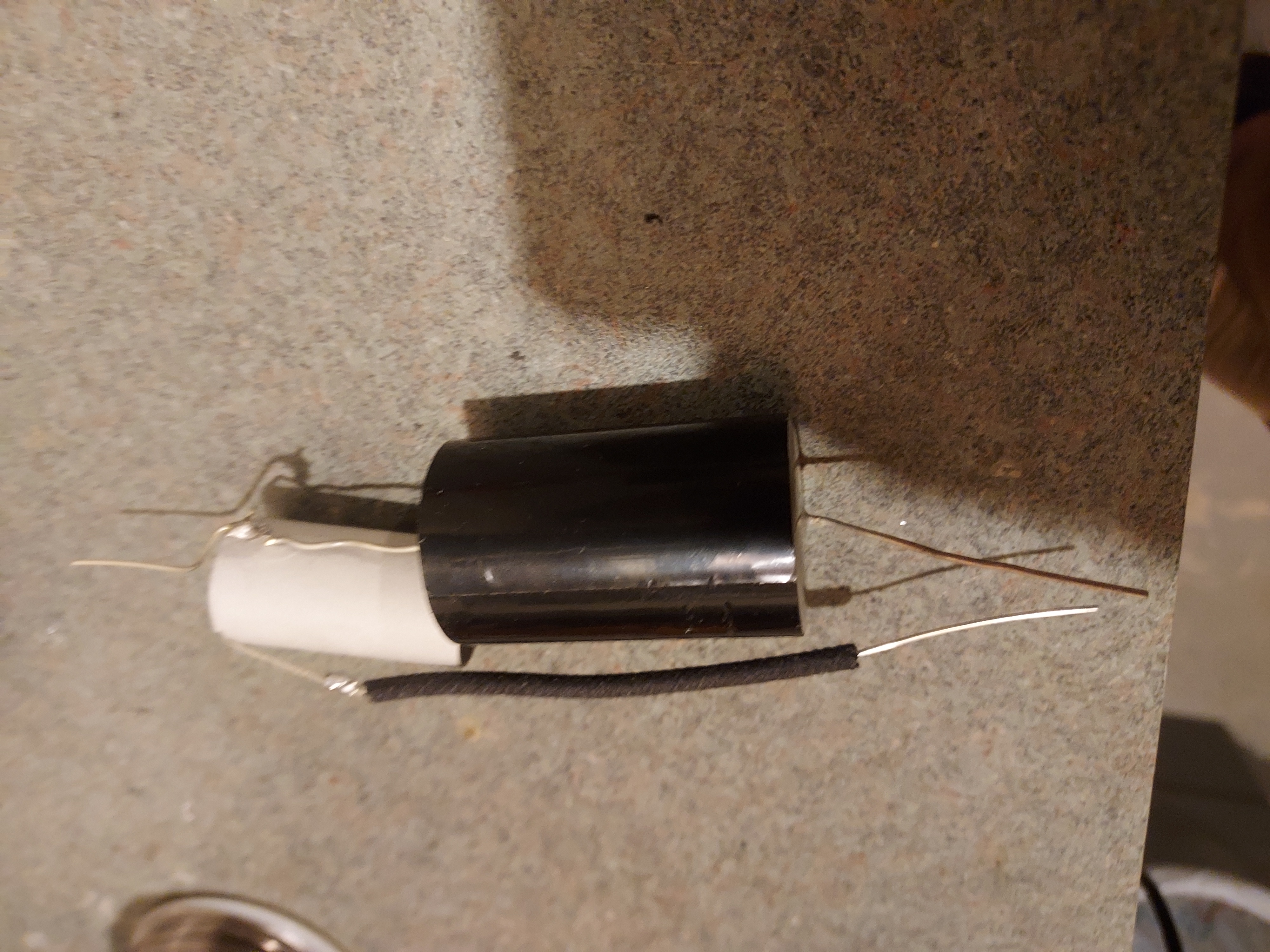
Then the Solen is also wrapped in fish paper to keep the positive wire from the 22uF cap from touching the aluminum.
It is done separately as the electrolytic cap is excentric towards the film cap, and its diameter is larger than the radious of the Solen, and so the resulting common wrap would not fit in the aluminum shell.
This way it does. The paper wrappings are secured with fabric glue and are reliably keeping the bare wires and the solder joints insulated.
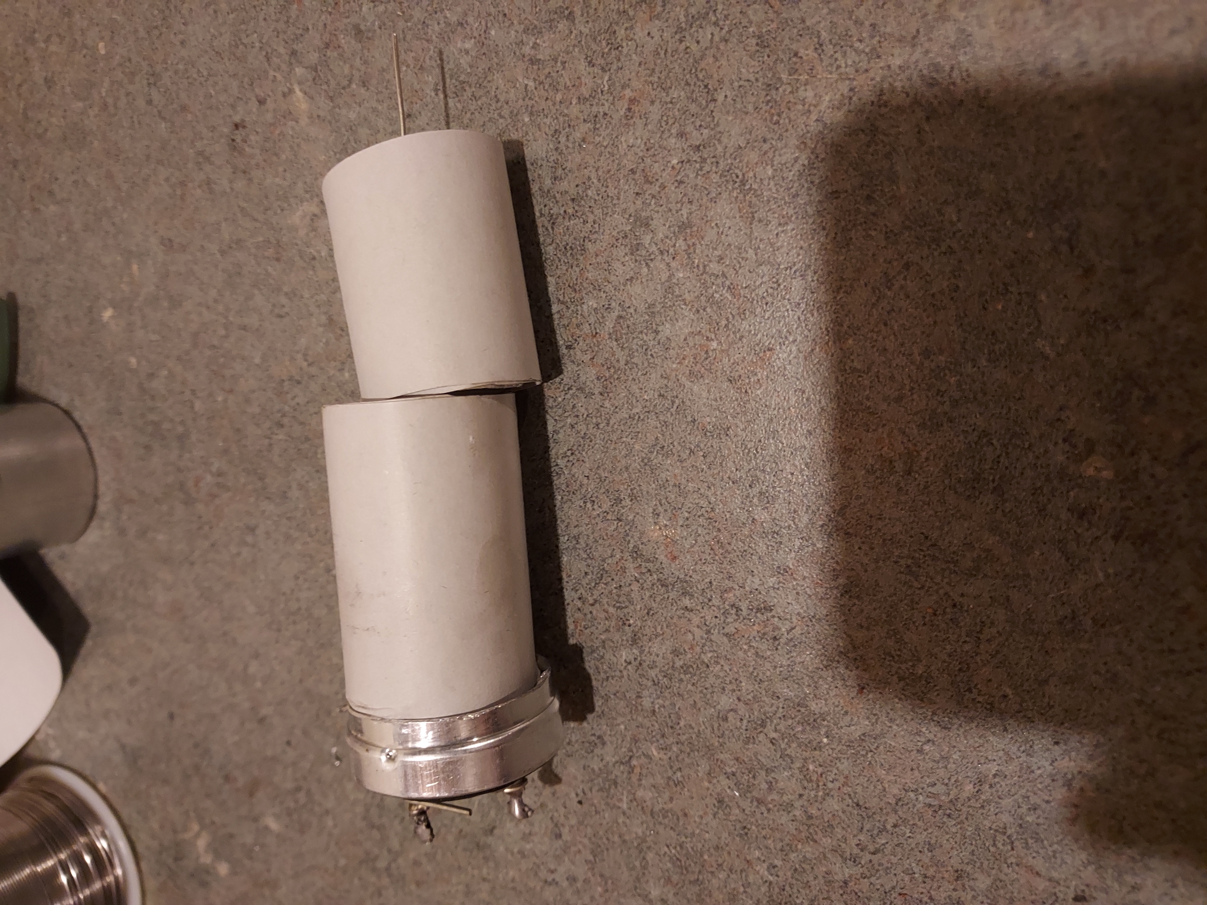
The common minus obviously was hard to aim to go through the rivet, so all it took was soldering lead wire to it, long enough so it could be easily aimed at the rivet hole, and then the rest just followed, even without pulling the lead wire.
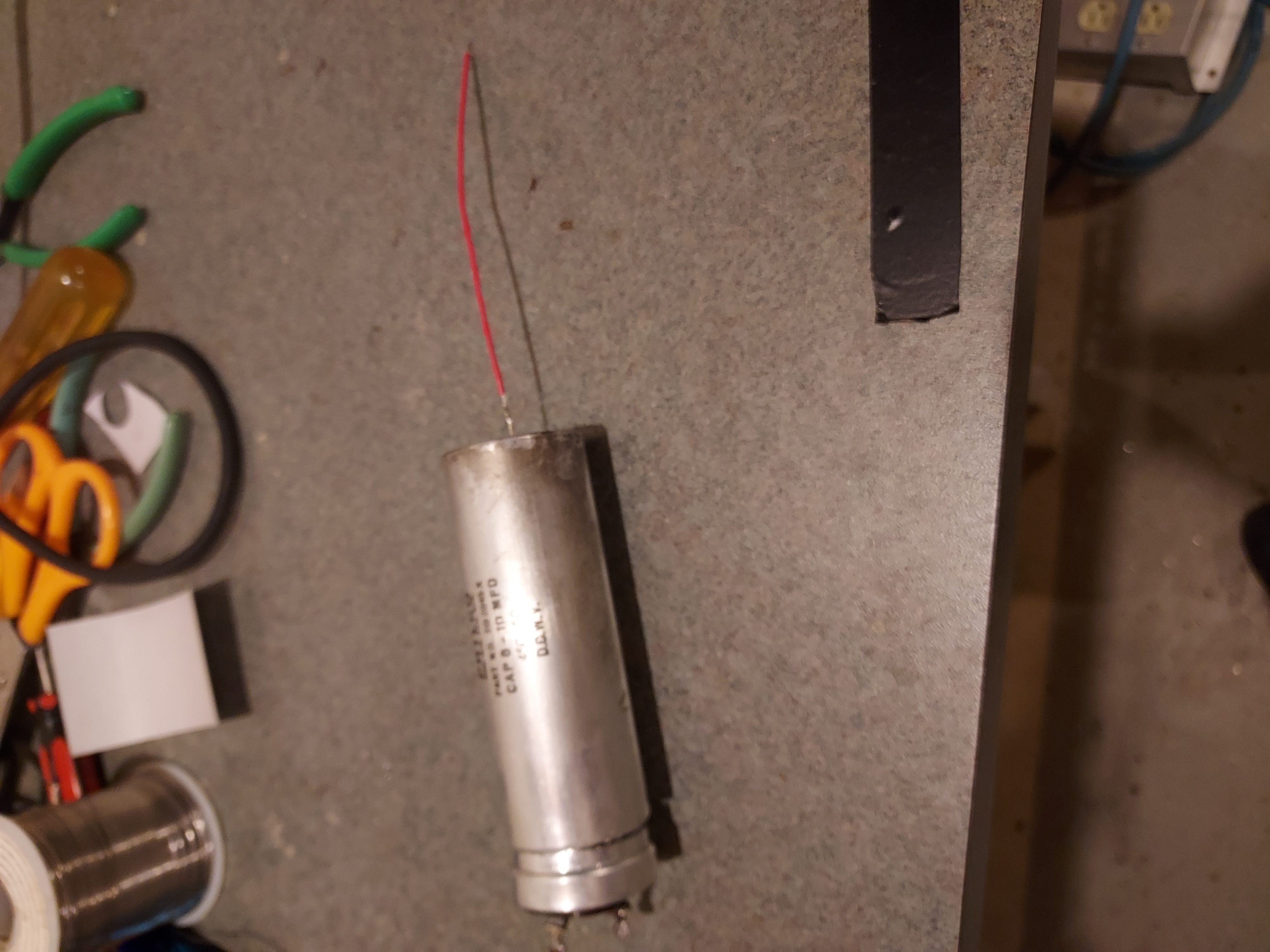
After glueing the case together, the terminals and the common minus were soldered.
Here's the common minus. It reliably makes the case the negative, so now it can be treated as was the original cap: using the lug slid under the cardboard shell touching the case and then clamped by the common dual clamp that holds the caps to the chassis.
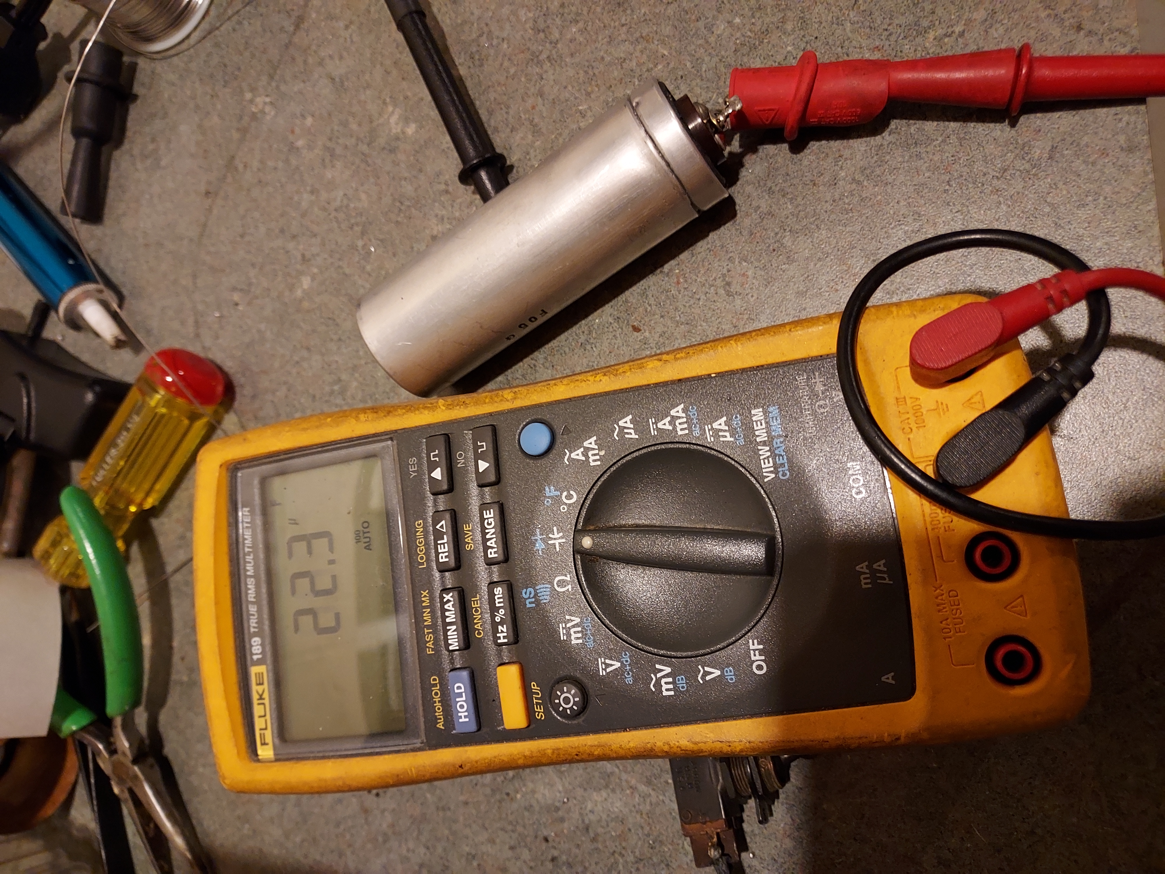
The meter shows 8uf and 22uF.
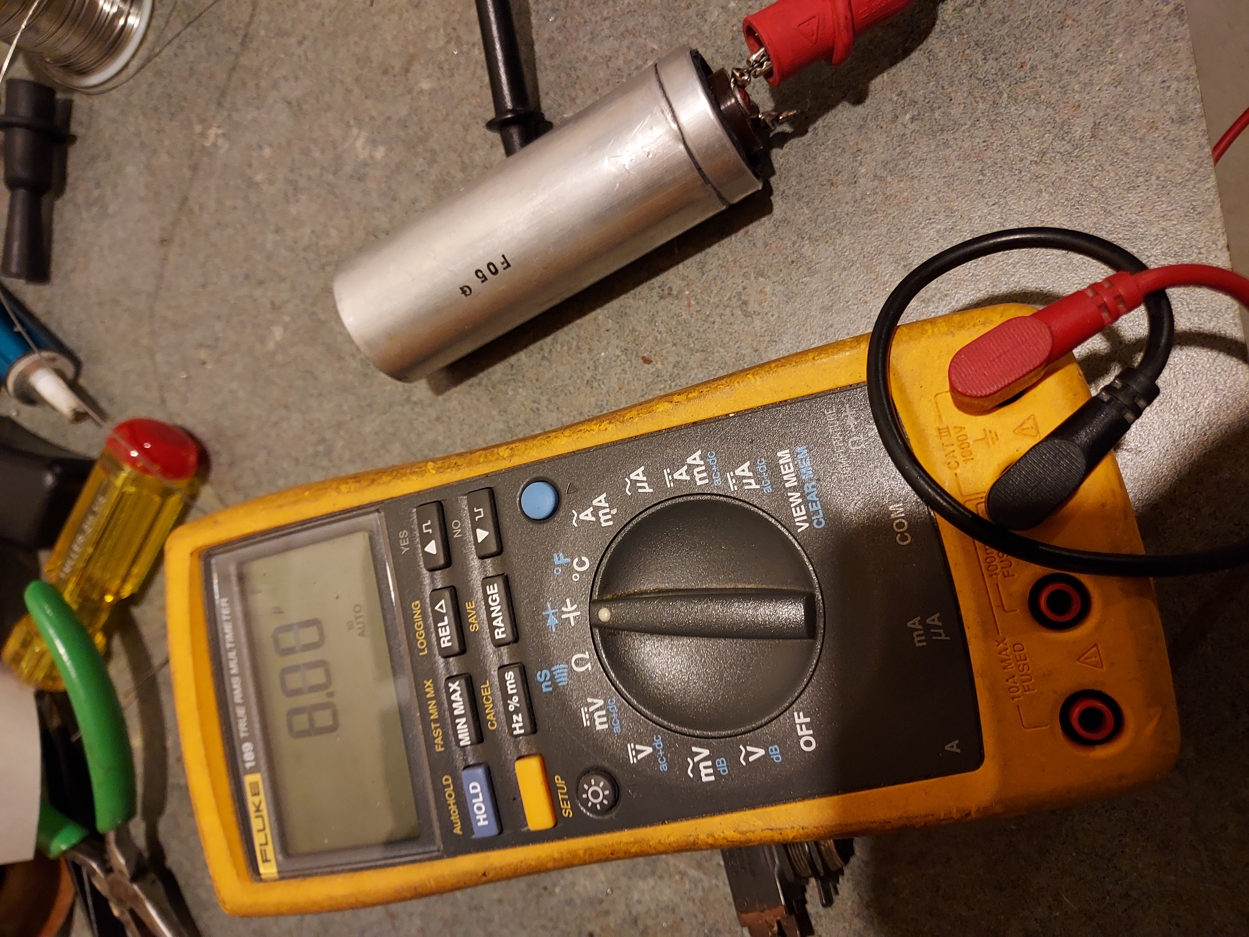
The two caps together.
People who do not drink, do not smoke, do not eat red meat will one day feel really stupid lying there and dying from nothing.
Posts: 16,533
Threads: 573
Joined: Oct 2011
City: Jackson
State, Province, Country: NJ
The caps are installed and the wiring is done.
No more new can or 50-s Atom caps. All more or less original.
This completes the recap and recarb.
This weekend will be the smoke test, then hopefully power-up etc.
People who do not drink, do not smoke, do not eat red meat will one day feel really stupid lying there and dying from nothing.
Posts: 16,533
Threads: 573
Joined: Oct 2011
City: Jackson
State, Province, Country: NJ
OK, so...
I checked the pwr xfmr output, high voltage - good, 5V to the 80's filament - good.
Put all the tubes, checked for the short B+ to GND/Centertap - good.
Turned on, waited for the B+ to rise to 150V or so, then after a while brought it up all the way.
Heard the reception noise, tuned to the local station, got somewhat distorted reception.
Noticed the shadowmeter worked great.
Then tried the tone control, and heard whistling in all positions.
Looked at the 77 1st AF stage, the grid wire was outside the shield, thought that would be it, but no, same behaviour.
Then I touched the 77's grid and saw faint violet glow.
I replaced the 77, and the reception came undistorted, and the tone control worked fine. No glow either. The tube that glowed was checked for gas....oh well.
I am still thinking if I Ineed to fix the speaker cone and spider.
Also the toggle switch (interstation noise suppression) does not work, so I will have to either fix it or replace it.
People who do not drink, do not smoke, do not eat red meat will one day feel really stupid lying there and dying from nothing.
Posts: 16,533
Threads: 573
Joined: Oct 2011
City: Jackson
State, Province, Country: NJ
I have just spoken to Rich Stamer; he indicated the spiders do not get repaired and a full re-cone would be what he would do. He keeps the voice coil impedance, but itself it also gets changed.
I looked at the cone again (well, there is a pretty detailed photo here up in the beginning of the thread): it has a few tears loosely smeared with cement, and the spider, to me, has to be replaced: I do not see a good way of repairing cracks in cardboard.
So I think I will send it out for a full re-cone.
I need to do it soon as Rich is going for a surgical procedure and will stop everything after mid-November till some time in February.
I guess I will align the radio first and then send the speaker out.
People who do not drink, do not smoke, do not eat red meat will one day feel really stupid lying there and dying from nothing.
Posts: 7,303
Threads: 269
Joined: Dec 2009
City: Roslyn Pa
It's all good! Just take the afternoon off jump in your ride and drive it over. It's not that far.
When my pals were reading comic books
I was down in the basement in my dad's
workshop. Perusing his Sam's Photofoacts
Vol 1-50 admiring the old set and trying to
figure out what all those squiggly meant.
Circa 1966
Now I think I've got!
Terry
Users browsing this thread: 1 Guest(s)
|
|
Recent Posts
|
|
Philco newbie with P-1891-WA console questions
|
| Well, I've been stumped at trying to get the first of 11 electrolytic capacitors. I got a schematic and have a list of t...Jeffcon — 07:54 PM |
|
Model 80 Antenna Issue?
|
| Thanks Gary and Rod.
I also found an article in the Philco Repair Bench under Service Hints and Tips, about installi...Hamilton — 12:32 PM |
|
Model 80 Antenna Issue?
|
| Hello Hamilton, here is a little information found in our Philco Radio Library at the bottom of the Home page. Hope it ...GarySP — 11:28 AM |
|
Model 80 Antenna Issue?
|
| I did as you suggested and touching the middle of the volume control did nothing so the coil has to be rewound. Any idea...Hamilton — 10:19 AM |
|
1949 Motorola 5A9M
|
| This would be the second portable in the "other radios" forum where I have a similar one in my collection. I h...Arran — 12:41 AM |
|
Looking for any info: 1977 Ford-Philco Console Hi-Fi Turntable and Radio
|
| Hi PittsburgTost.
The record changer looks like a Garrard or BSR (Likely Garrard). The spindles just pull out and pu...MrFixr55 — 11:57 PM |
|
Looking for any info: 1977 Ford-Philco Console Hi-Fi Turntable and Radio
|
| Hello PittsburghToast ,
Welcome aboard and it looks like gary may have something for you !
now if I dig through my se...radiorich — 11:35 PM |
|
Model 80 Antenna Issue?
|
| You are kind of on the right path. You can touch the grid cap of the Detector/Oscillator 36 tube. I'm expecting a respon...RodB — 08:48 PM |
|
Looking for any info: 1977 Ford-Philco Console Hi-Fi Turntable and Radio
|
| Welcome to the Phorum, PittsburghToast! I found an old thread that my interest you regarding the quality and worth of P...GarySP — 08:48 PM |
|
Looking for any info: 1977 Ford-Philco Console Hi-Fi Turntable and Radio
|
| Welcome to the Phorum!
:wave:
We do not have anything on that unit in our digital library. There is a Sam's Photof...klondike98 — 08:47 PM |
|
Who's Online
|
There are currently 976 online users. [Complete List]
» 1 Member(s) | 975 Guest(s)
|
|
|

|
 
|


![[-] [-]](https://philcoradio.com/phorum/images/bootbb/collapse.png)


