03-07-2023, 06:14 PM
https://philcoradio.com/library/download...l.%202.pdf
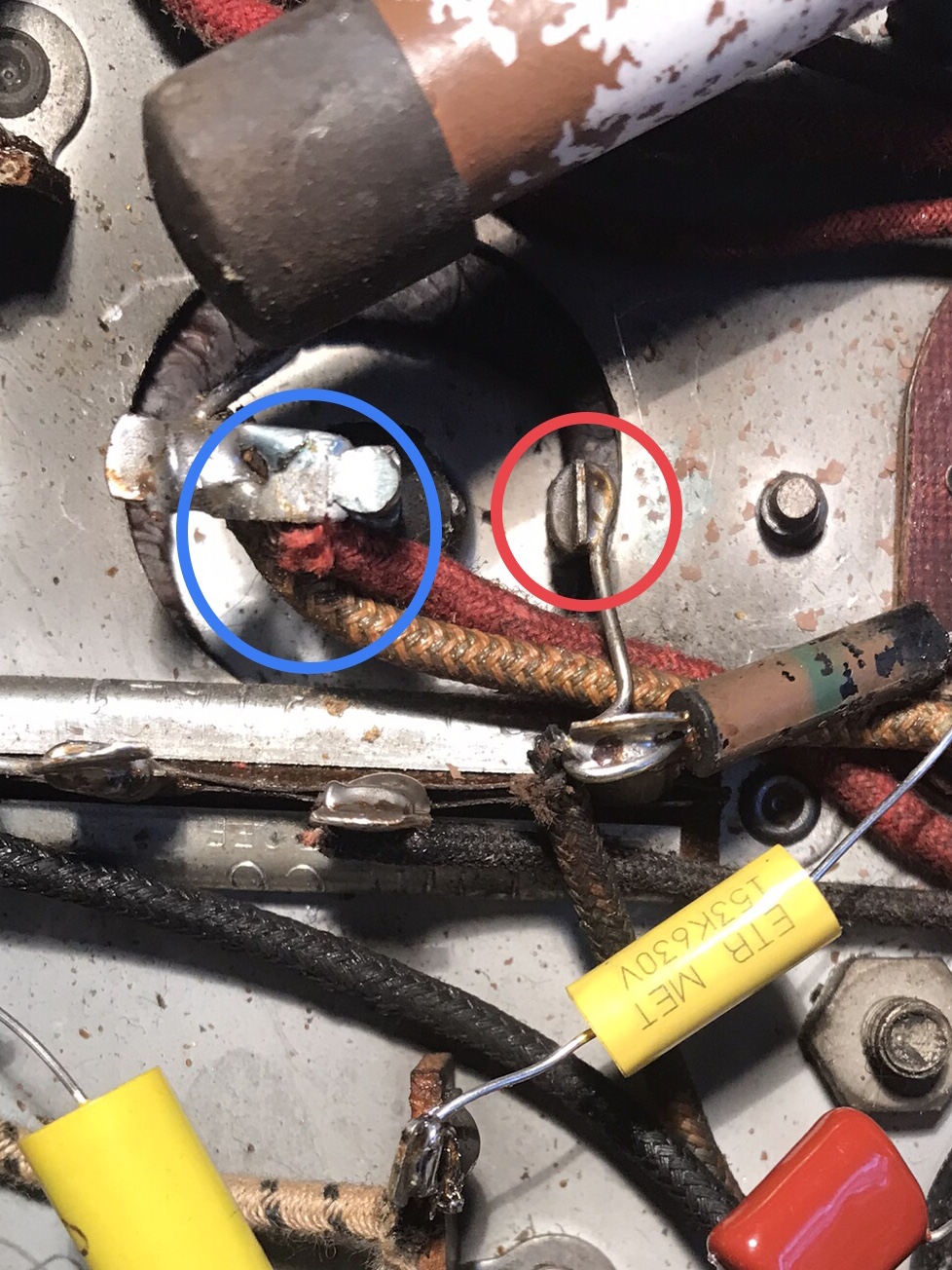
I’m working on a Philco 38-09 and I have a question regarding one of the electrolytic caps, part #45. The enclosed photo showing the blue circle is the 25 mfd cap with two wires attached to it. The two-tone yellow/green wire goes to the field coil and the red goes to Pin 6 of the 5Y4 tube where it is connected with a black wire that goes to the power transformer. I’m assuming that is my + connection for my replacement cap and the red circle is my - connection.
I’m still new to this hobby and I hoped someone could confirm whether I’m correct and enlighten me as to the purpose of why this cap is connected to the 5Y4 tube and not directly into the power transformer.


![[-] [-]](https://philcoradio.com/phorum/images/bootbb/collapse.png)


