Posts: 45
Threads: 6
Joined: Apr 2023
City: Temecula
State, Province, Country: CA
Sorry for the newbie question... I've been searching and have not yet achieved enlightenment... or maybe this is so basic no one talks about it?
But I have a new signal generator in one hand and a tube radio in the other, and they need connecting.
I understand that at a minimum I need to put a capacitor in line with the "hot" lead to avoid toasting the signal generator.
Fine, but what's a good way to do this?
- I doubt that a string of alligator clips and caps flopping around on the workbench is right.
- Could make up a lead with a cap soldered in, but the idea of a solid-lead cap with no strain reliefs flopping around in a cable doesn't sound right either.
- And if this is SOP, wouldn't there be ready-made test leads for this? Not finding any...
Posts: 5,160
Threads: 273
Joined: Nov 2012
City: Wilsonville
State, Province, Country: OR
Depending on the radio and the band being aligned there are different cap values called for in alignment instructions. Don’t know how much difference it can make however. I just use the alligator clip approach.
Posts: 45
Threads: 6
Joined: Apr 2023
City: Temecula
State, Province, Country: CA
As long as you touch the right place, maybe little importance. Slip and touch B+, that won't do the generator any good!
I may need to learn about alignment, for starts I just want to inject signals ..
Posts: 182
Threads: 8
Joined: Apr 2023
City: Roanoke
State, Province, Country: Virginia
klondike98 Wrote:I just use the alligator clip approach.
So do I, but have made my own with very short leads and booted small clips for such purposes.
Dale H. Cook, GR/HP/Tek Collector, Roanoke/Lynchburg, VA
https://plymouthcolony.net/starcity/radios/
Posts: 45
Threads: 6
Joined: Apr 2023
City: Temecula
State, Province, Country: CA
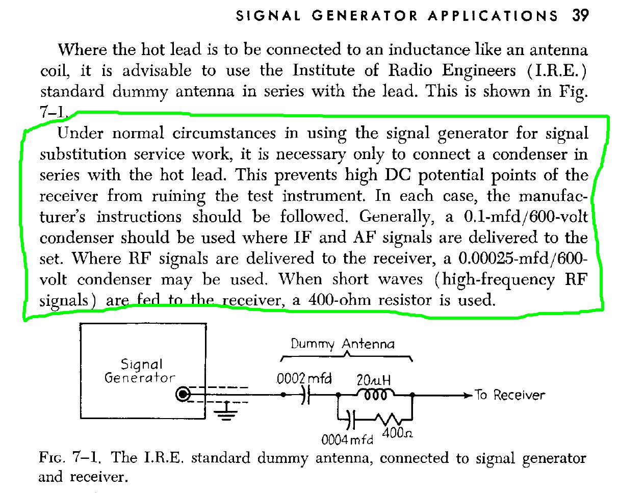
For the record, here's the advice from Elements of Radio Servicing (1947):

Posts: 864
Threads: 50
Joined: Feb 2013
City: Shenandoah,
State, Province, Country: Pennsylvania
Pat, I’m using an old Heathkit SG-8 that was my dad’s. I reworked it by replacing the original connectors on the front of the cabinet with BNC type which is more compatible with newer test leads. While doing that, I inserted a cap to the center pin or hot side so it’s always there and I don’t need to worry about cobbling together anything before connecting to a radio. If I remember, I think I used a .01 mfd/630 volt unit. Works great on anything I’ve used it on so far!
Ron
Bendix 0626. RCA 8BX5. RCA T64
Philco 41-250. Philco49-500
GE 201. Philco 39-25
Motorola 61X13. Philco 46-42 Crosley 52TQ
Philco 37-116. Philco 70
AK 35 Philco 46-350
Philco 620B. Zenith Transoceanic B-600
Philco 60B. Majestic 50
Philco 52-944. AK 84
Posts: 182
Threads: 8
Joined: Apr 2023
City: Roanoke
State, Province, Country: Virginia
462ron Wrote:I’m using an old Heathkit SG-8 that was my dad’s. I reworked it by replacing the original connectors on the front of the cabinet ...
About 40 years ago I used a number of pieces of vacuum-tube EICO and Conar test equipment that my father built from kits in the '60s when I was young. I eventually replaced almost all of them with GR and Heathkit instruments, but still use two of them (EICO 625 emission tester and 950A LCR bridge) - the rest are shelf queens. Some of them used the 2-conductor button mic jacks that were so common on EICO and Heathkit equipment in the '60s. I never replaced any of those jacks because 40 years ago parts jobbers were still common all over the country and I could get those plugs easily and cheaply for making custom cables.
Dale H. Cook, GR/HP/Tek Collector, Roanoke/Lynchburg, VA
https://plymouthcolony.net/starcity/radios/
Posts: 1,119
Threads: 44
Joined: Feb 2015
City: Roseville, MN
I use the loosely coupled approach. I feed the generator signal to a coil of wire through a .1mfd cap. Then move the coil close to the radio to get the correct signal strength. When I have to inject the signal I use a .05mfd cap with an alligator clip soldered to a lead.


![[-] [-]](https://philcoradio.com/phorum/images/bootbb/collapse.png)


