Posts: 16,533
Threads: 573
Joined: Oct 2011
City: Jackson
State, Province, Country: NJ
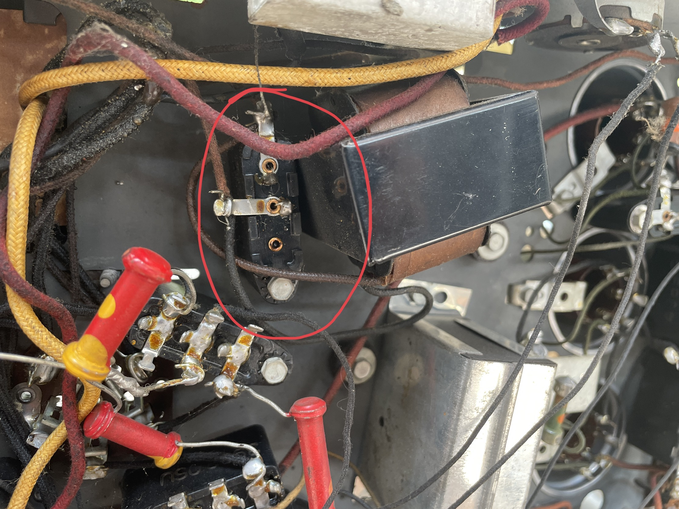
On the side of that backelite block there is a number. It is the identifier.
Then you go to "Philcorepairbench.com" or Ray Bintliff's book, or post it here and someone will tel you what it is.
People who do not drink, do not smoke, do not eat red meat will one day feel really stupid lying there and dying from nothing.
Posts: 5,182
Threads: 276
Joined: Nov 2012
City: Wilsonville
State, Province, Country: OR
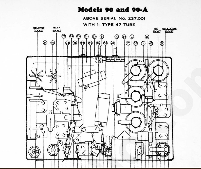
We have the schematic for the single 47 version in our library if that helps.
https://philcoradio.com/library/index.ph...chematics/
On the side of that bake light block cap will be a number. That should tell you what is inside it. See:
https://philcoradio.com/library/index.ph...lock-data/
Posts: 5,182
Threads: 276
Joined: Nov 2012
City: Wilsonville
State, Province, Country: OR
Mike was responding at the same time as I was. Chuck’s Philco repair bench site is no longer active. If the block is not in the Service Bulletin I referenced, post the number here and someone with the book will respond. I think it’s out if print now.
Posts: 31
Threads: 9
Joined: Nov 2010
City: Woodbury, MN
The number on the side of the mystery capacitor was 4989J which was superseded by 4989SU (0.1uf). It is wired directly across the choke (#55) on the parts list. Is not on the schematic for the middle version of the model 90 but is shown on the late version.
Thank you both very much for your help!! I think I have the information I need to proceed.
Jim
Posts: 16,533
Threads: 573
Joined: Oct 2011
City: Jackson
State, Province, Country: NJ
If it was wired across the filter choke, you could take it out.
It was a thought that a cap across the choke could pass just enough ripple to compensate the residual ripple remaining after the LC filter, due to the fact that the currents in the choke and the cap are phased 180 degrees to each other when the voltage is the same, so they would cancel out.
The practice confirmed this is not that efficient and simply increasing the cap after the choke is way more efficient at suppression of the ripple and, therefore, the hum.
The limits for the cap capacitance that the rectifier tube has applies only to the first cap, connected directly to its Cathode, but the cap after the choke could be increased quite a bit as the ripple current across it is fairly small. So while the cap 56 should be 6uF as required (small variations are OK as the tolerance itself is 20%) the cap 57 could be 10uF, 22uF or even more. And the one in question is simply not needed.
People who do not drink, do not smoke, do not eat red meat will one day feel really stupid lying there and dying from nothing.
Posts: 31
Threads: 9
Joined: Nov 2010
City: Woodbury, MN
Thanks again for all the help and advice!
Posts: 181
Threads: 8
Joined: Apr 2023
City: Roanoke
State, Province, Country: Virginia
klondike98 Wrote:Chuck’s Philco repair bench site is no longer active.
Chuck's site has been preserved in the WABAC Machine (incorrectly spelled "Wayback" on the site) at the Internet Archive:
https://web.archive.org/web/202300000000...rbench.com
Dale H. Cook, GR/HP/Tek Collector, Roanoke/Lynchburg, VA
https://plymouthcolony.net/starcity/radios/
Posts: 5,182
Threads: 276
Joined: Nov 2012
City: Wilsonville
State, Province, Country: OR
Thanks Dale, I forgot about that site


![[-] [-]](https://philcoradio.com/phorum/images/bootbb/collapse.png)


