Posts: 5
Threads: 2
Joined: Nov 2023
City: LA (CASTRILLON) LAGUNA
State, Province, Country: Spain
Hello!
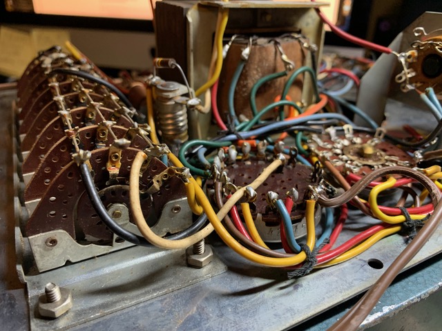
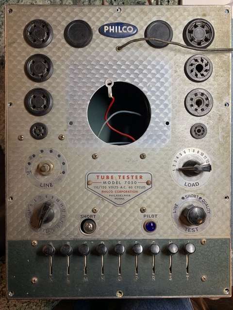
I'm trying to restore a 7050 that is missing a few things inside. I have the schematic but some good photos of the interior would help a lot. Can you pass me some please? Thank you!
Posts: 16,533
Threads: 573
Joined: Oct 2011
City: Jackson
State, Province, Country: NJ
Is the 220 Ohm across the galvanometer ok?
People who do not drink, do not smoke, do not eat red meat will one day feel really stupid lying there and dying from nothing.
Posts: 5
Threads: 2
Joined: Nov 2023
City: LA (CASTRILLON) LAGUNA
State, Province, Country: Spain
There is no galvanometer and no resistor ?
Posts: 181
Threads: 8
Joined: Apr 2023
City: Roanoke
State, Province, Country: Virginia
EDDIE_MUTANTE Wrote:There is no galvanometer and no resistor ?
You are correct - galvanometers are uncalibrated devices with center zero with no current - they are used only to indicate a balance condition when used with an instrument such as a Wheatstone bridge or a laboratory potentiometer. Your 7050 has an ammeter (probably a milliammeter) which is calibrated (however simply) into good and replace zones. That is what has a 220 Ohm shunt resistor across its movement.
Dale H. Cook, GR/HP/Tek Collector, Roanoke/Lynchburg, VA
https://plymouthcolony.net/starcity/radios/
(This post was last modified: 11-04-2023, 12:48 PM by DaleHCook.)
Posts: 5
Threads: 2
Joined: Nov 2023
City: LA (CASTRILLON) LAGUNA
State, Province, Country: Spain
Hello Dale.
What I mean (sorry for my horrible English) is that somebody has tryed to use the 7050 for something else and almost all inside has gone.
I have read the instructions to "calibrate" the line and I have rebuild the 6X5GT circuit with one diode and the resistors involved on it. I put one amp meter in parallel with the 220ohm resistor (R107 in the schematic) and connect my varistor regulated at 115Vac (50Hz here). I have 30Vac at the anode and 394 micro amperes. What I'm trying to calculate is the range of the milliamperimeter that uses the the 7050. As the needle must on the center with the meter I think that I need a 1mA amp meter, but will be great that somebody could measure that on a working unit. I have read here that the resistance of that instrument is around 50 ohm, but that don't help me too much.
A greeting!
Posts: 181
Threads: 8
Joined: Apr 2023
City: Roanoke
State, Province, Country: Virginia
Eddie -
I hope someone that else can help you because I do not own a 7050.
Dale H. Cook, GR/HP/Tek Collector, Roanoke/Lynchburg, VA
https://plymouthcolony.net/starcity/radios/
Posts: 5
Threads: 2
Joined: Nov 2023
City: LA (CASTRILLON) LAGUNA
State, Province, Country: Spain
Thank you very much Dale.
I have poste this in various threats about the 7050 in this forum, I don't know why it have end here.
A greeting!
Posts: 16,533
Threads: 573
Joined: Oct 2011
City: Jackson
State, Province, Country: NJ
Well, the modern "analog" meters do use Weston/D'Arsonval galvanometer. To make it into the ammeter a shunt is placed across it, which is why I asked about the shunt resistor.
But the bare system, the magnet, the pivot and the wire frame (coil) with the attached pointer is, well, the Weston galvanometer.
https://phys.libretexts.org/Courses/Geor...nstruments
People who do not drink, do not smoke, do not eat red meat will one day feel really stupid lying there and dying from nothing.
Posts: 5,182
Threads: 276
Joined: Nov 2012
City: Wilsonville
State, Province, Country: OR
Looking at the pictures in your " Introduce Yourself" post it appears there is a lot missing from this tester. Perhaps someone here will have one and they can give you a photo of the underside of the chassis.
Posts: 1
Threads: 0
Joined: Dec 2023
City: Phoenix
State, Province, Country: AZ
Hello Eddie -
(My first post so I'm feeling my way through the Phorum process).
My 7050 is currently in disrepair... most notably I obtained it with a non-working meter movement (or as you referenced, a galvanometer). Multiple pictures are posted of the internals you were looking for.
Since my need is to find a replacement meter I too am in in search of the current rating of the meter for the 7050. The meter that was inside my unit was severely damaged and am unable to obtain a full scale current reading from it. All other channels of search have met with a dead end.
Looking for anyone else out there having a Philco 7050 that can help Eddie and me out with this information.
Thanks!
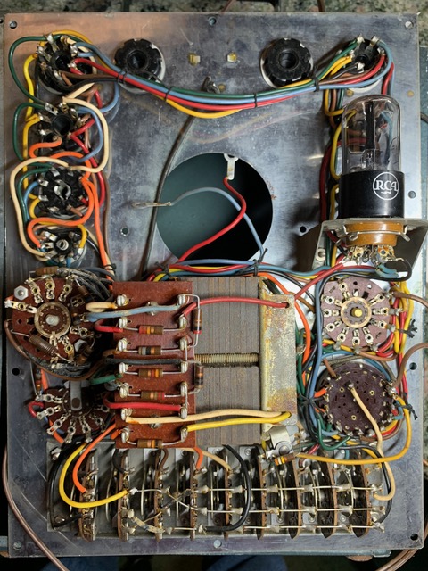
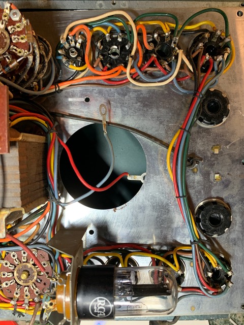
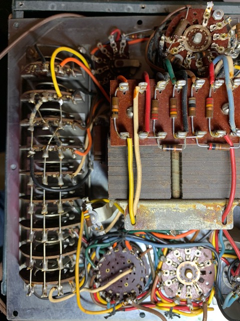
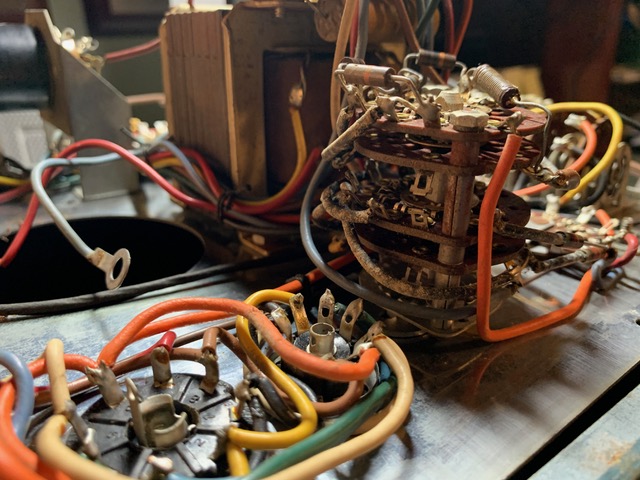
Users browsing this thread: 1 Guest(s)
|
|
Recent Posts
|
|
Philco 42-345 Restoration/Repair
|
| Thank you Rodb and Gary for helping with clarification on these capacitors. Other than the Tiny 630volt one I'm not sure...osanders0311 — 10:17 PM |
|
1949 Motorola 5A9M
|
| Hello All;
I found the CMB41L down in the basement, it is definitely a 1950-51 model, the capacitors have date codes ...Arran — 07:48 PM |
|
Philco 42-345 Restoration/Repair
|
| Hi, all the caps I order, other than the electrolytics, are of the 630V rating. No worries on it being too high, and no ...gary rabbitt — 05:46 PM |
|
Philco 42-345 Restoration/Repair
|
| Hi, there's a lot to consider when designing these circuits so you shouldn't have a lot of concern when replacing caps. ...RodB — 02:03 PM |
|
Philco 42-345 Restoration/Repair
|
| I have ordered and received new caps for this radio and hope I've ordered the correct ones. I tried matching them to the...osanders0311 — 11:35 AM |
|
Philco newbie with P-1891-WA console questions
|
| Hello Jeff ,
Far as the Electrolytic capacitors go here is a list of parts.
that will work . I like using Nichicon and...radiorich — 09:50 PM |
|
Philco newbie with P-1891-WA console questions
|
| Well, I've been stumped at trying to get the first of 11 electrolytic capacitors. I got a schematic and have a list of t...Jeffcon — 07:54 PM |
|
Model 80 Antenna Issue?
|
| Thanks Gary and Rod.
I also found an article in the Philco Repair Bench under Service Hints and Tips, about installi...Hamilton — 12:32 PM |
|
Model 80 Antenna Issue?
|
| Hello Hamilton, here is a little information found in our Philco Radio Library at the bottom of the Home page. Hope it ...GarySP — 11:28 AM |
|
Model 80 Antenna Issue?
|
| I did as you suggested and touching the middle of the volume control did nothing so the coil has to be rewound. Any idea...Hamilton — 10:19 AM |
|
Who's Online
|
| There are currently no members online. |

|
 
|


![[-] [-]](https://philcoradio.com/phorum/images/bootbb/collapse.png)


