Posts: 322
Threads: 60
Joined: Mar 2007
City: Toledo
State, Province, Country: OH
Posts: 322
Threads: 60
Joined: Mar 2007
City: Toledo
State, Province, Country: OH
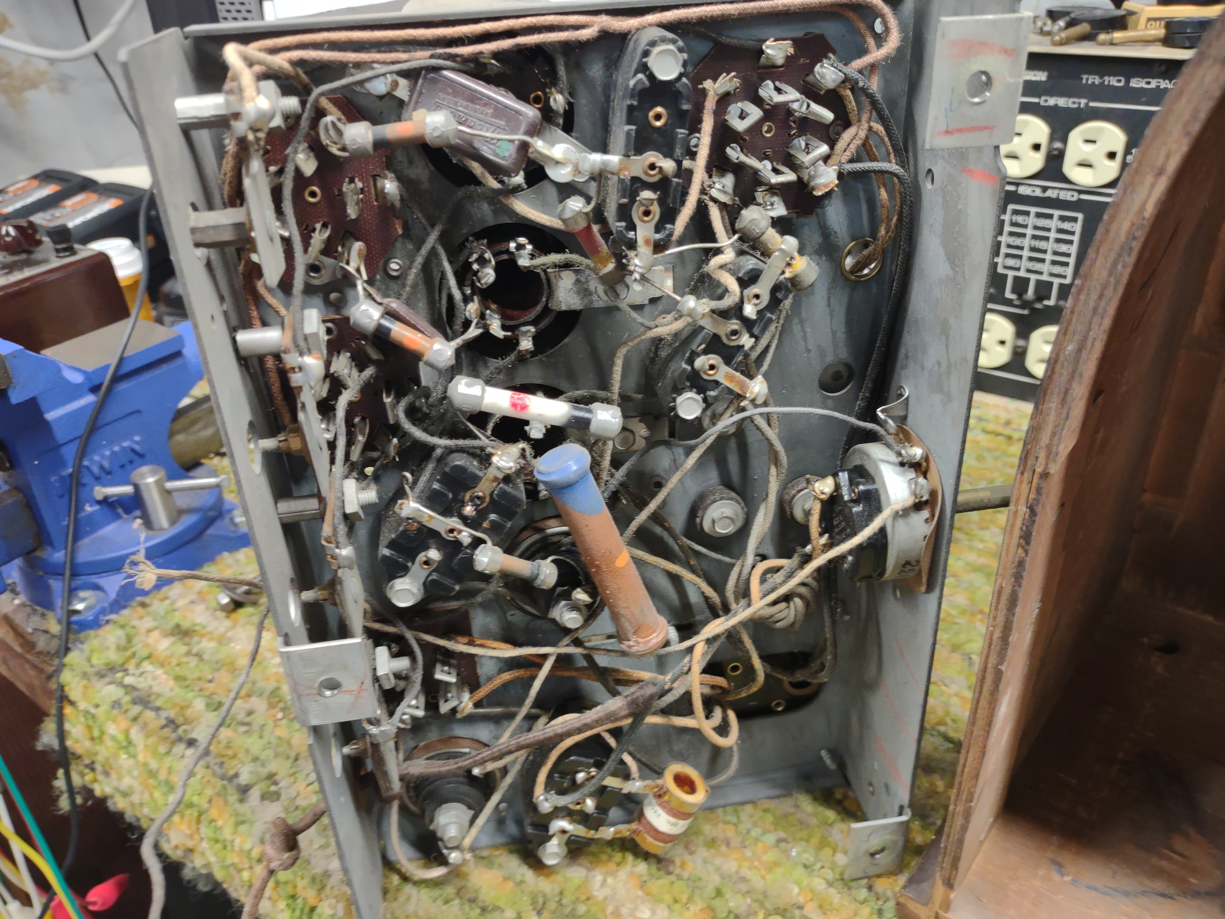
Right off the bat I have a question. As you can see in the first picture at the bottom there is 1 bakelite block cap with a wirewound resistor across it yet in the nostalgia schematic/layout they show 2 blocks and no resistor across either one. I looked thru the bulletins listed here on the forum but did not see anything relating to this fact. Has anyone seen this version of the chassis before and can maybe point me in the right direction as to a correct schematic?
http://www.nostalgiaair.org/Resources/843/M0013843.htm
(This post was last modified: 07-22-2024, 06:03 PM by
Jim Dutridge.)
Posts: 205
Threads: 5
Joined: Sep 2005
City: Newark, Ohio
I think you have a model 84, not 80.
Hope this helps .
Posts: 322
Threads: 60
Joined: Mar 2007
City: Toledo
State, Province, Country: OH
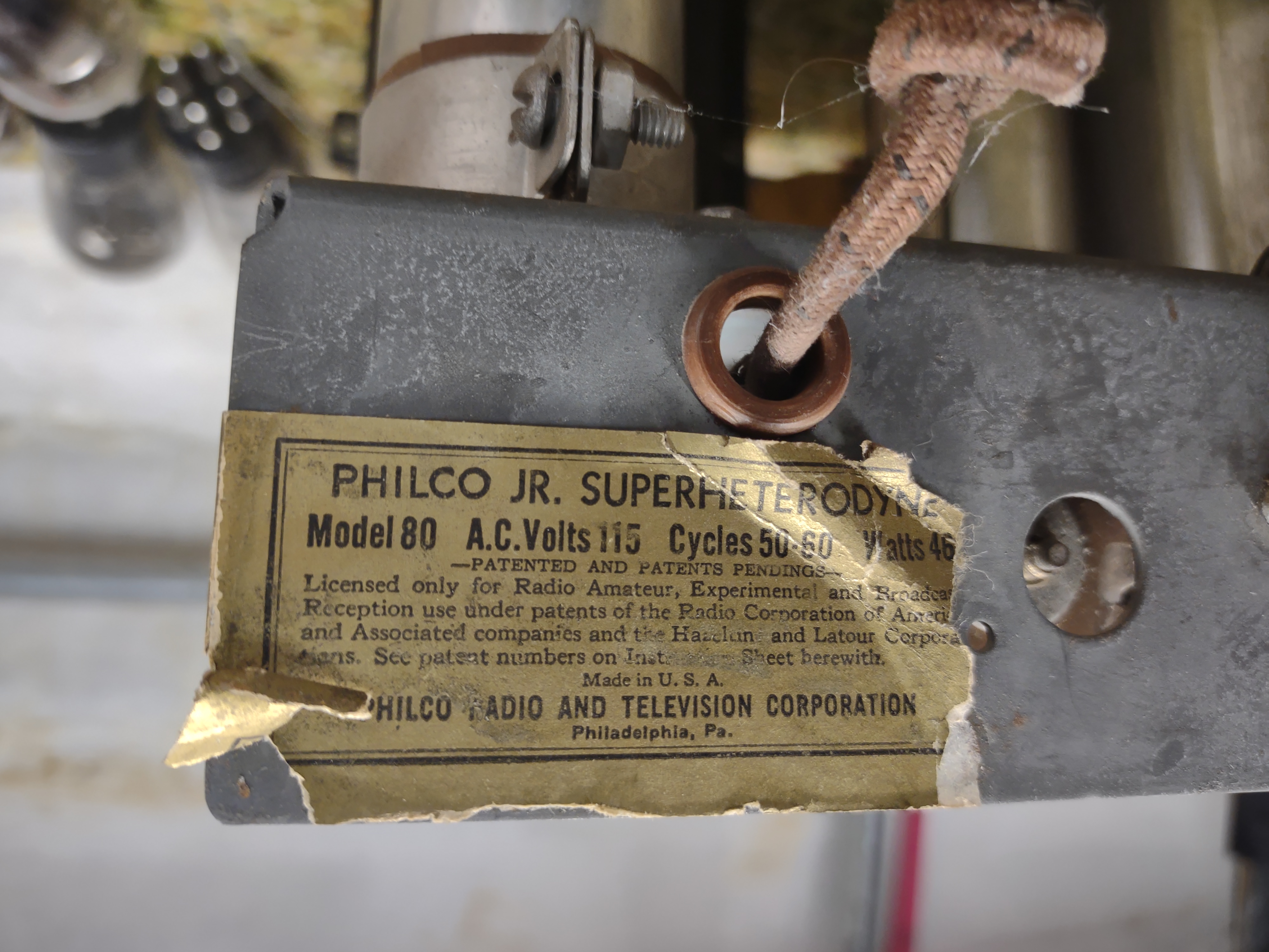
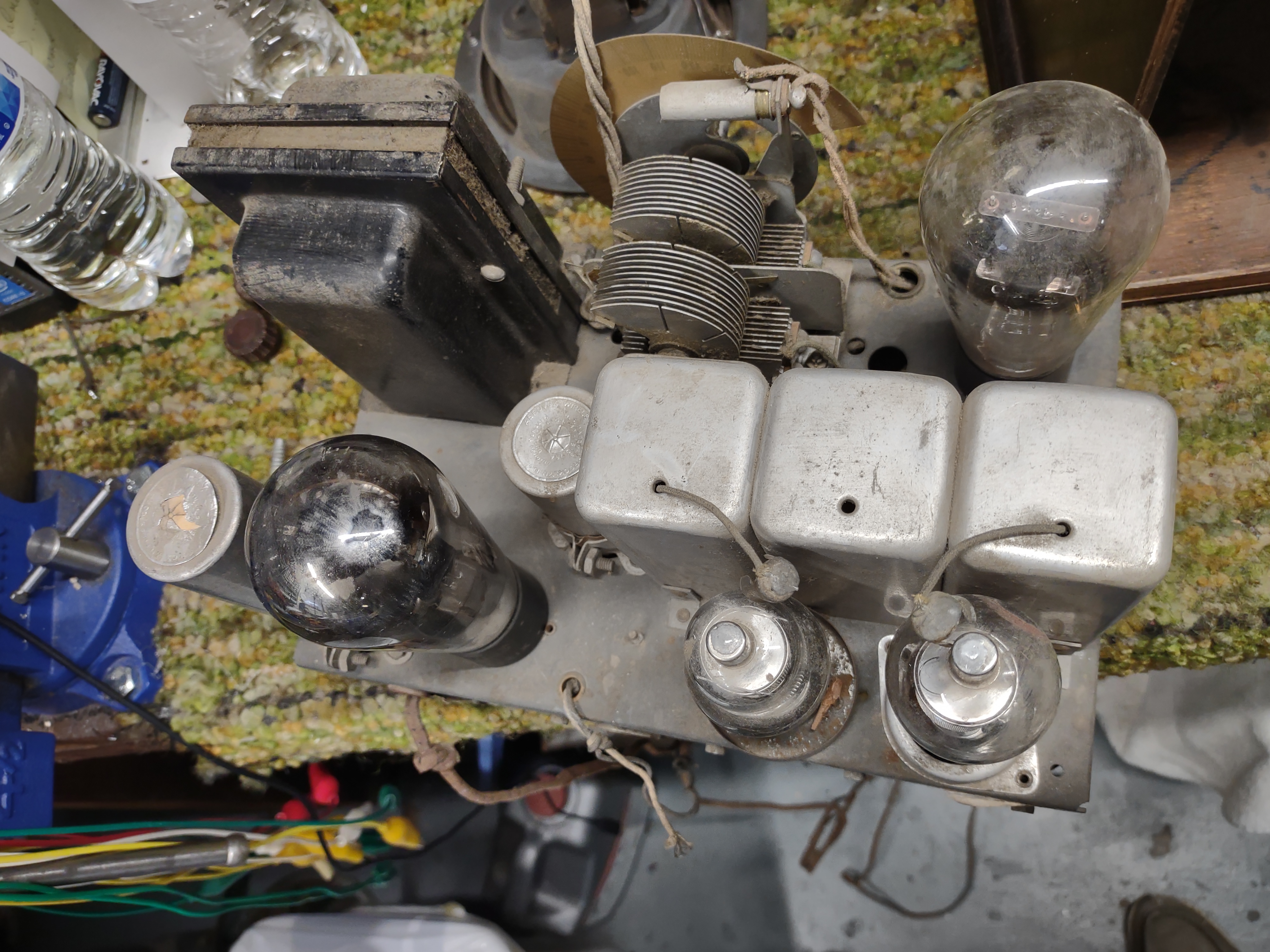
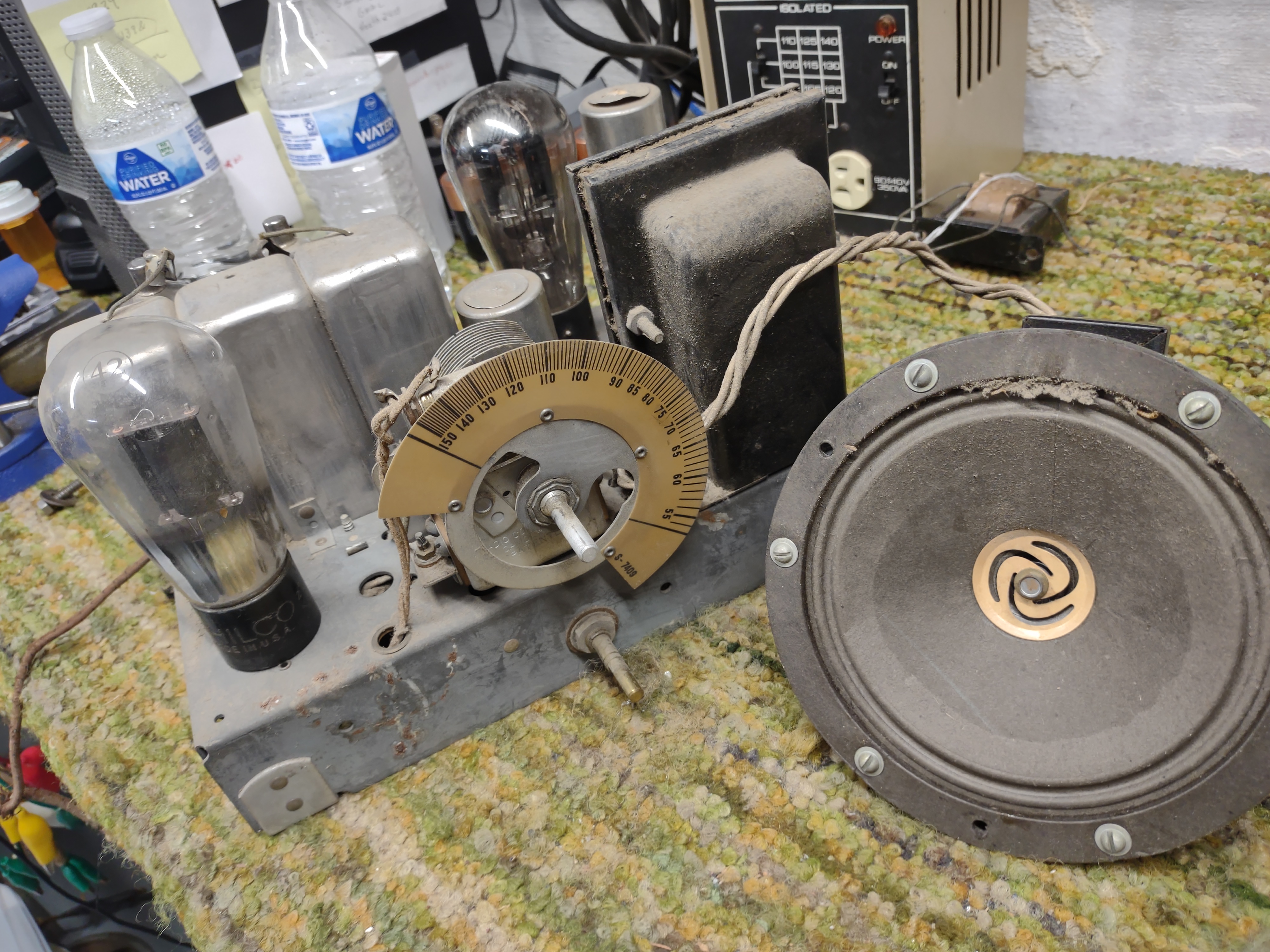
Well the chassis layout for the 84 still does not match what I have since block #32 is not in my chassis. My cabinet is a dead ringer for the model 80 so maybe whatever chassis I have actually fits the 80 cabinet. Several other reasons why I don't think this is a 84. First there is no gimmick wrapped around the volume control wiper arm like what is used in the 84, second this chassis uses type 36 tubes versus 77's (yes , they are interchangeable), third resistor #9 was changed from a 9K used in the 80 to a 13K used in the 84. #9 in this chassis is a 9K.
I think I might just call this a model 80 with an undocumented circuit change unless someone can come up with a better idea. Anyway, on with the repairs.
Edit: Interesting that the model 81 layout shows cap block 35 with that wirewound resistor across it but the rest of the layout does not match.
(This post was last modified: 07-23-2024, 12:25 PM by
Jim Dutridge.)
Posts: 322
Threads: 60
Joined: Mar 2007
City: Toledo
State, Province, Country: OH
Why I didn't notice this before I have no clue but the sticker clearly shows it to be a model 80 so I'm going with this is a chassis with undocumented changes.
(This post was last modified: 07-23-2024, 12:37 PM by
Jim Dutridge.)
Posts: 7,303
Threads: 269
Joined: Dec 2009
City: Roslyn Pa
Tis an 80 check the service bulletins for updates in the circuit.
https://philcoradio.com/library/download...%20140.pdf
When my pals were reading comic books
I was down in the basement in my dad's
workshop. Perusing his Sam's Photofoacts
Vol 1-50 admiring the old set and trying to
figure out what all those squiggly meant.
Circa 1966
Now I think I've got!
Terry
Posts: 322
Threads: 60
Joined: Mar 2007
City: Toledo
State, Province, Country: OH
Posts: 1,264
Threads: 32
Joined: Jan 2014
City: Wellborn Florida
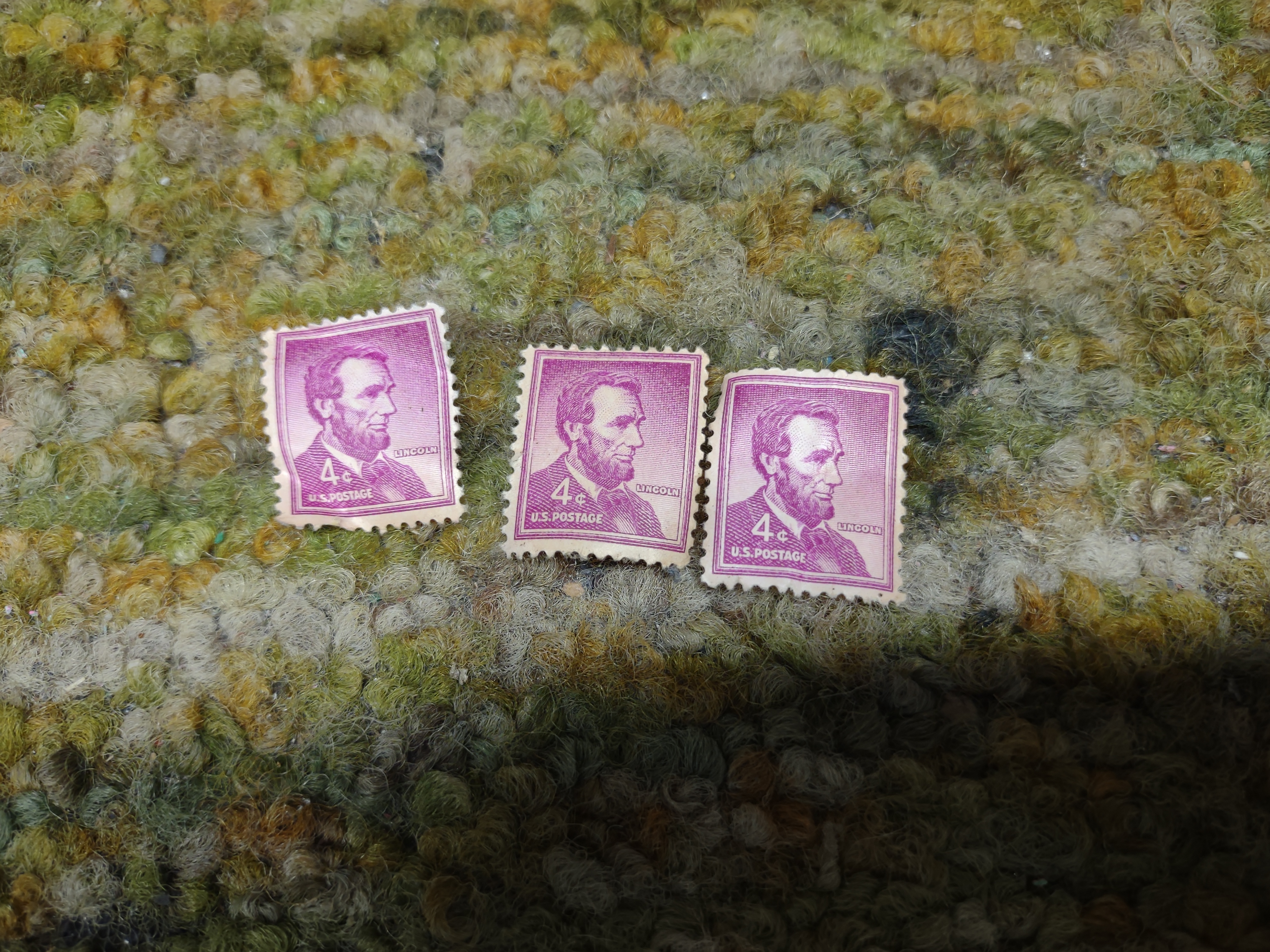
The stamps are probably worth more than the radio. The 4 cent stamp is from 1954. I was in the first grade that year. David
Posts: 1,264
Threads: 32
Joined: Jan 2014
City: Wellborn Florida
Posts: 7,303
Threads: 269
Joined: Dec 2009
City: Roslyn Pa
To rebuild that block You'll need a .015mfd 630v line bypass cap and a 10mfd 50v ecap. The ecap + goes to chassis ground - to ww resistor/hv ct. This will replicate the original circuit. This block was used post run 5.
When my pals were reading comic books
I was down in the basement in my dad's
workshop. Perusing his Sam's Photofoacts
Vol 1-50 admiring the old set and trying to
figure out what all those squiggly meant.
Circa 1966
Now I think I've got!
Terry
Posts: 322
Threads: 60
Joined: Mar 2007
City: Toledo
State, Province, Country: OH
For that cap block I used a .01uF Y2 safety cap but as you can see in my first picture the electrolytic cap you are referring to does not exist in my chassis.
As to progress, I have already rebuilt the blocks and replaced resistors that were OOT but I am waiting on a replacement resistor for the 16K (#11) to get here from Digikey which should be Monday. Then I can complete installing the second filter cap and the 16K and 1M resistors.
As for the gimmick around the wire from the volume control center tap, how tight do the windings need to be or does it not matter?
(This post was last modified: 07-28-2024, 12:52 PM by
Jim Dutridge.)
Posts: 7,303
Threads: 269
Joined: Dec 2009
City: Roslyn Pa
> For that cap block I used a .01uF Y2 safety cap but as you can see in my first picture the electrolytic cap you are referring to does not exist in my chassis.
Yes I understand that the later versions of the 80 and all of the 81 & 84's don't use that 10mfd cap. But I suspect that it was a cost cutting measure to replace it w/a matching .015mfd cap. What it does is filter the negative leg of the power supply. That's why 10mfd is much better than .015mfd and now days you get them in a small enough size to fit within the block. The voltage rating is low as it's just has the bias voltage across it may be 16v so a 35v cap would be fine.
> As for the gimmick around the wire from the volume control center tap, how tight do the windings need to be or does it not matter?
I don't a 80 chassis apart but I do have a 84. It has 2 turns over about 1 3/4". It's there to coupe some more oscillator signal thru to the antenna to improve strong signal mixing. Remember there is no agc/avc to help control the gain any of the stages.
When my pals were reading comic books
I was down in the basement in my dad's
workshop. Perusing his Sam's Photofoacts
Vol 1-50 admiring the old set and trying to
figure out what all those squiggly meant.
Circa 1966
Now I think I've got!
Terry
Posts: 322
Threads: 60
Joined: Mar 2007
City: Toledo
State, Province, Country: OH
1 3/4" length for that gimmick huh. Looks like I need to redo mine then. I just wound 3 turns tightly. My other parts are out for delivery today via FedEx so I'll redo my gimmick then. Also, I was rereading the service hints on the Philco repair bench site for the 80 and I failed to notice a part about changing the circuit of the detector/oscillator cathode. Unfortunately the picture referenced on the page is not viewable. Can someone tell me what changes were made?
(This post was last modified: 07-29-2024, 12:01 PM by
Jim Dutridge.)
Posts: 7,303
Threads: 269
Joined: Dec 2009
City: Roslyn Pa
Some will play with the value of #6 by lowering it down to 8K if the oscillator is a bit sluggish.
YMMV
When my pals were reading comic books
I was down in the basement in my dad's
workshop. Perusing his Sam's Photofoacts
Vol 1-50 admiring the old set and trying to
figure out what all those squiggly meant.
Circa 1966
Now I think I've got!
Terry
Posts: 322
Threads: 60
Joined: Mar 2007
City: Toledo
State, Province, Country: OH
Thank you. Now if only Fedex can find my package that was supposedly delivered today to my house, which it was not.


![[-] [-]](https://philcoradio.com/phorum/images/bootbb/collapse.png)


