Posts: 23
Threads: 3
Joined: Feb 2021
City: Durham
State, Province, Country: NC
I'm working on a Code 121 Philco 71B that has suffered extensive rodent damage underneath the chassis. I have resleeved the wiring as best I could. Bakelites have been restuffed. Electrolytic capacitors and safety caps replaced. Tubes checked and all good now (had to replace two of them). Filter capacitor metal box components have been restuffed. Micas were not replaced.
I'm able to pick up local (within 5-15 miles) stations all along the band but with low volume. The only way I can increase the volume is to place my finger on the 44 RF tube cap.
Another way to increase the volume is to jumper a lead from the antenna connection (with antenna in place) to the cap of the 44.
There is no static or squeals. Sound is pretty clean but again volume is low.
I have checked solder connections and those seem to be fine. I have checked voltages on all the tubes and they are within 5% of the specs EXCEPT I am getting a 2.56 reading on the 6.3 volt filaments. Also getting 6.6 and 7.9 voltages on the rectifier (80) 5 volt filaments. Plate voltages on the rectifier are 292 volts per plate.
Another observation is the Part No 59 (13,000 ohm-3 watt resistor) gets very hot after even a few minutes of being powered on. I replaced the big dogbone one with a smaller 3 watt resistor and it gets very hot as well. I have noted that the resistor decreases in ohms (down to 10 K or so) when it gets hot and when the set cools down, the ohms go back to nearly normal but now reads around 12,500 ohms.
On the 44 audio tube, the P-K reading is high (measures 101 (spec is 50)
Was curious if anyone has also encountered these situations and what are some things that I should now be investigating ?
(This post was last modified: 08-04-2024, 03:38 PM by
dmblackburn.)
Posts: 714
Threads: 9
Joined: Apr 2018
City: S. Dartmouth
State, Province, Country: MA
This is a rusted chassis. ANY grounds that are made via a rivet should be soldered to the chassis, use an active flux and a large soldering copper, preheat the chassis to get solder to flow.
A wiring error in the electrolytic can be a problem check those connections. Solder blobs, wire snips can cause shorts.
Check all RF/OSC coils for not only correct resistance but leakage between the coils. ANY leakage is an indication that celluloid liners have become acidic and are leaking between the coils. Cols will have to be rewound and insulated with Kapton tape or PETE.
Some tubes with grid caps develop a poor connection at the grid cap, re-solder...
GL
Chas
Pliny the younger
“nihil novum nihil varium nihil quod non semel spectasse sufficiat”
Posts: 1,411
Threads: 71
Joined: Oct 2007
City: Linn Creek, MO
If stations only come in while touching the grid cap of the RF tube, that is a pretty sure sign the antenna transformer has an open winding. On to the filament voltages. Be sure to use the AC scale on your meter, read from filament pin to filament pin. not filament to chassis ground. Last, the plate voltage of the 1st audio is probably OK. The plate is supplied through a couple of high value resistors, your modern meter does not load the circuit as much as the meters used back in the day, giving a higher reading.
Steve
M R Radios C M Tubes
Posts: 1,151
Threads: 47
Joined: Feb 2015
City: Roseville, MN
I'm having a difficult time finding part 59 on the schematic. I see it on the part location diagram. Try telling us what it's connected to. Why did you replace it? It's obvious that the circuit it's connected to is drawing way too much current so we should look at that.
Posts: 23
Threads: 3
Joined: Feb 2021
City: Durham
State, Province, Country: NC
Thank you gentlemen for your input. I will investigate further based on your comments.
Chas, you are right, I do have a rusty chassis I will plan to solder those grommet connections after rust cleanup to clean metal
.
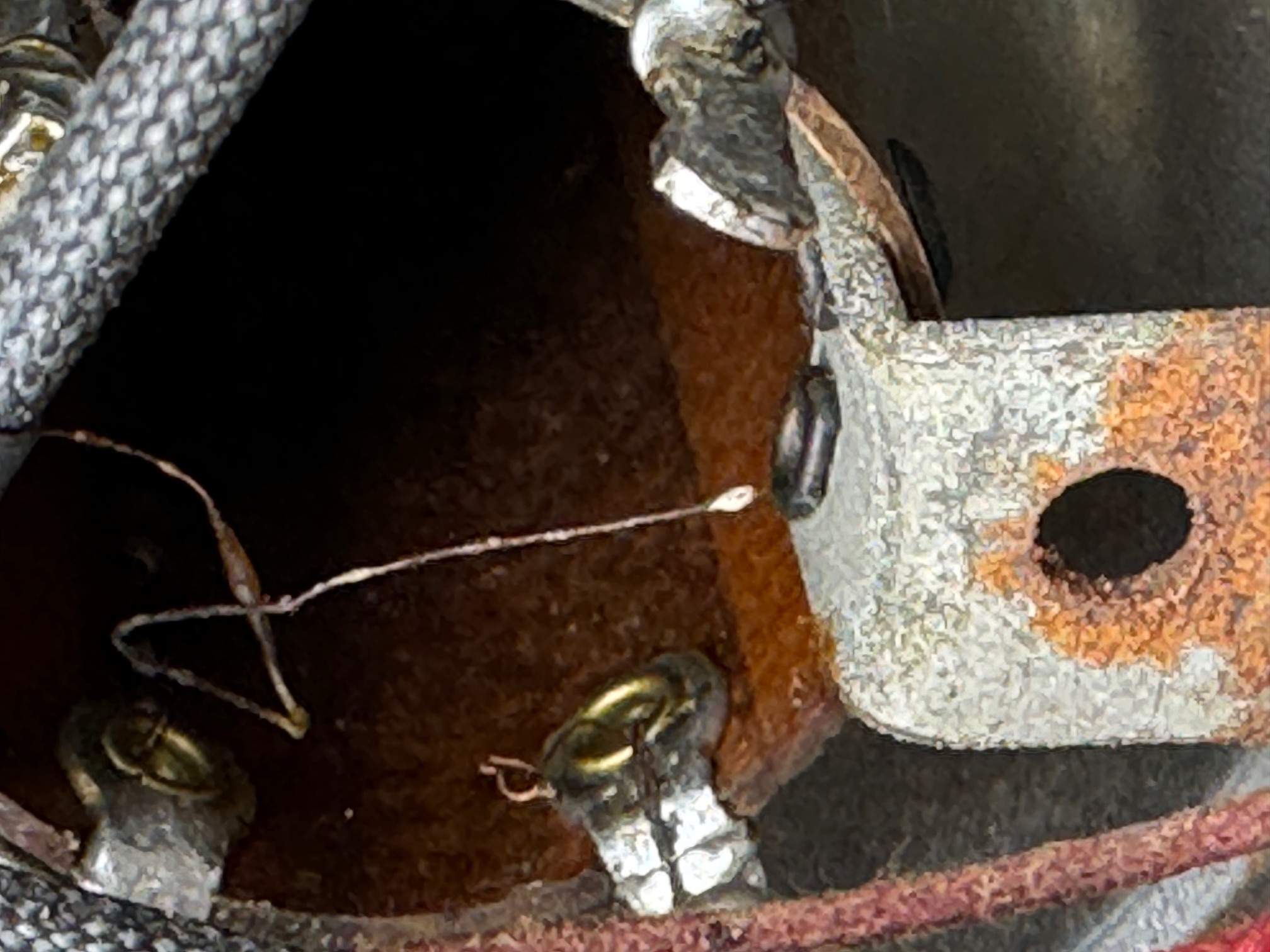
Steve, I have included a photo of the antenna coil, and I believe you are correct about an open winding. It looks as though a wire has broken loose. It also looks like a bit of solder on the end of one wire. Maybe this was an attempt to repair it earlier.


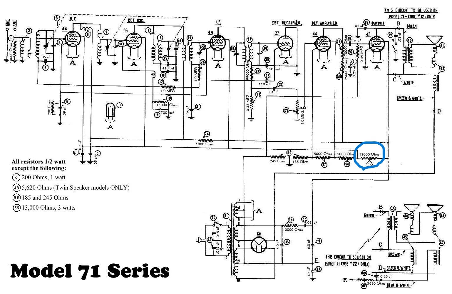
Rod, I have attached a schematic with the PN 59 circled in light blue. I replaced the dogbone with a smaller resistor as it was testing about 10,500 ohms.
Posts: 23
Threads: 3
Joined: Feb 2021
City: Durham
State, Province, Country: NC
Update : i decided to take this radio off the isolation-dim bulb-variac setup and plug into the wall. Previously my variac was set to 115 volts. My wall voltage is 120 volts.
What a surprise- now I'm getting full volume on all the local stations. Sometimes the volume decreases then increases. I have also noticed in doing this, I am getting pretty severe static when the HVAC and HVAC fan are running.
I keep monitoring the ohms on the 13K resistor (PN59) with the set off and now the value is up (approximately 14-14.5 K)
Posts: 1,268
Threads: 11
Joined: Jul 2020
City: Greenlawn
State, Province, Country: NY
Hi DM Blackburn,
First off, if the Heater voltages are still low, check the transformer wiring. Per the schematic, the heater winding for all the tubes except the 80 should connect to leads # 3 and 5. Lead 4 is the center tap for this winding. This connection and the center tap for the 80 Plate winding, lead 9 goes to ground through a 250Ohm resistor. This is common in sets of this vintage, as this is how "C-" is developed, and the belief that grounding the center tap of the winding for the heaters for the tubes other than the rectifier reduced hum, as the 6V tubes were originally designed for car radios and operated on DC there. By the 1940s, both of these practices ended.
Measure the voltage on both sides of the 13K resistor in question. One side should read about 250 V. The other should be about 80-100. If much lower or zero v, check cap #21, a 0.5uF cap. It may be shorted. If so, it kills screen voltage for all tubes except the 42 output tube.
"Do Justly, love Mercy and walk humbly with your God"- Micah 6:8
"Let us begin to do good"- St. Francis
Best Regards,
MrFixr55
Posts: 23
Threads: 3
Joined: Feb 2021
City: Durham
State, Province, Country: NC
Thank you for this info.
I measured the voltages on each side of the 13K resistor : 286 VDC on the side next to the RF choke and 97.5 VDC on the other side. This resistor gets very hot to the touch but no smoking or melting apparent. Would it help if I go to a higher wattage ?


![[-] [-]](https://philcoradio.com/phorum/images/bootbb/collapse.png)


