1930s Stewart-Warner Tombstone Radio need help identifying model number
Posts: 325
Threads: 34
Joined: Dec 2019
City: Elkhart
State, Province, Country: Indiana
Hello everyone today I took a trip up to Michigan and picked up a 1930s Stewart-Warner Tombstone Radio that I need help finding a model number for it because all of the model number information tags are either damaged or missing from the radio and I know there's a website out there that you can use to find a radio model number by typing in the tube line up but I can't for the life of me remember the name of the website and I need this radio's model number to look up some service data for it for electrically restoring it, and also locating a replacement tuning dial for it because the original phoenolic tuning dial is broken and I need to replace it to help make this radio functional and complete again.
See pictures below.
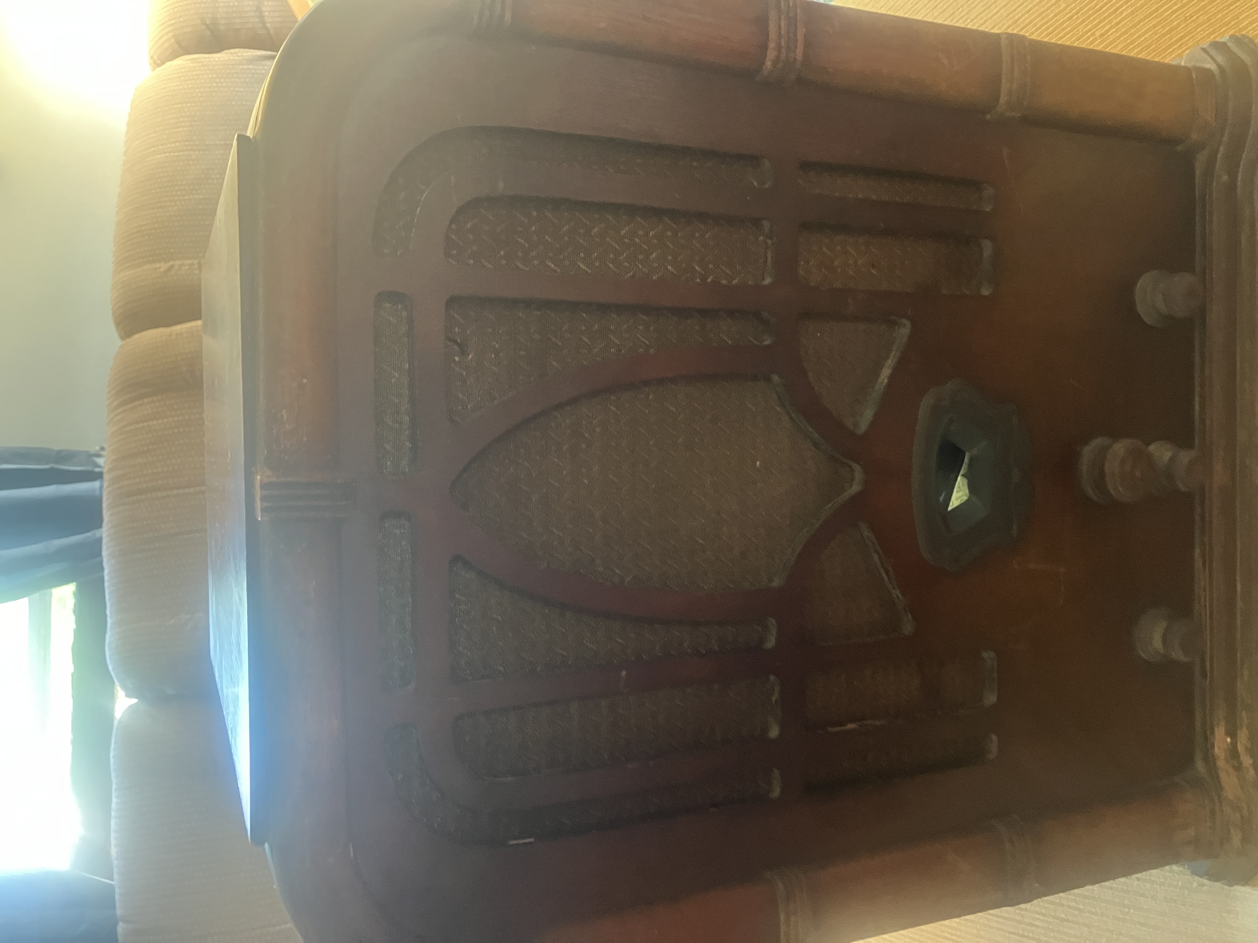
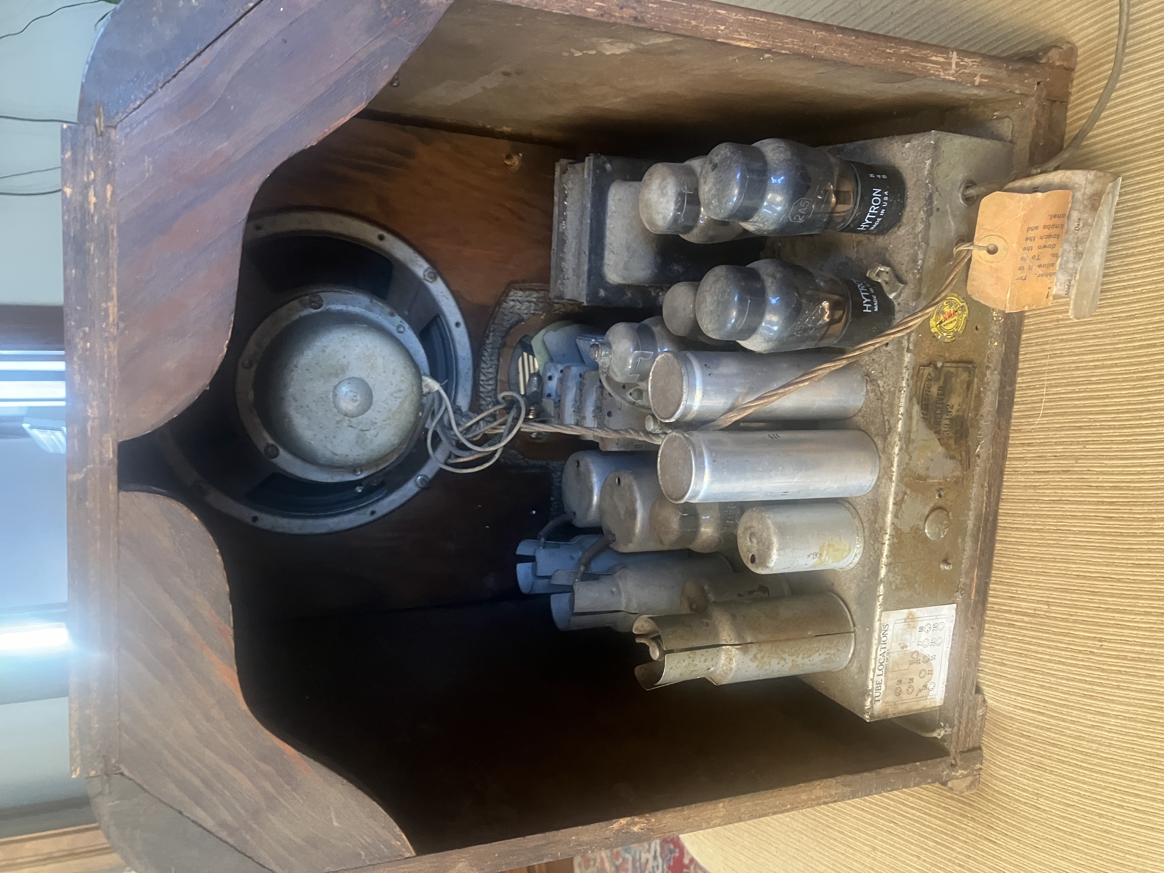
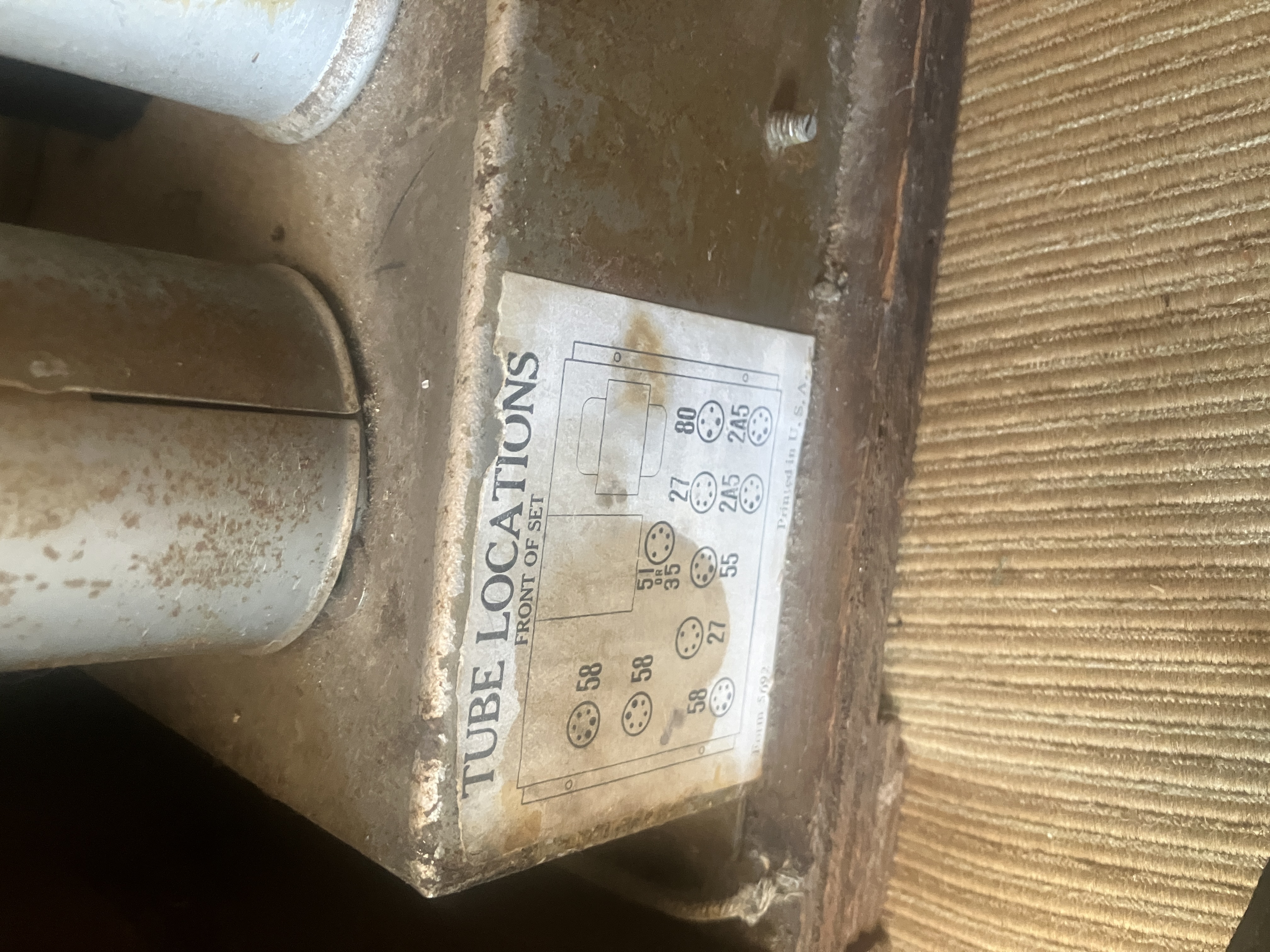
Do any of you guys recognize this radio and what model it might be?
I appreciate any help you can give me.
Thanks.
Posts: 1,119
Threads: 44
Joined: Feb 2015
City: Roseville, MN
Try radiomuseum.org for the tube list. That's a beast!
Posts: 16,476
Threads: 573
Joined: Oct 2011
City: Jackson
State, Province, Country: NJ
People who do not drink, do not smoke, do not eat red meat will one day feel really stupid lying there and dying from nothing.
Posts: 325
Threads: 34
Joined: Dec 2019
City: Elkhart
State, Province, Country: Indiana
OK, yeah, I meant to say Stewart-Warner not Stromberg-Carlson, I tend to get those brands mixed up.
Posts: 16,476
Threads: 573
Joined: Oct 2011
City: Jackson
State, Province, Country: NJ
People who do not drink, do not smoke, do not eat red meat will one day feel really stupid lying there and dying from nothing.
Posts: 4,858
Threads: 54
Joined: Sep 2008
City: Sandwick, BC, CA
Really, I used to get Setchell Carlson mixed up with Stromberg-Carlson, but never mixed up either one with Stewart Warner. Stewart Warner was in Chicago (Belleville, Ontario in Canada) whereas Stromberg Carlson was in Rochester, New York (Toronto, Ontario in Canada). I don't think Setchell Carlson set were ever marketed in Canada, and they don't seem to have been as prolific in terms of models, or production, as either Stromberg-Carlson nor Stewart Warner. Stewart Warner used to manufacture speedometers and other dashboard instruments for cars, and even manufactured grease guns for a time, so car enthusiasts are familiar with the company, some are even surprised to find out that they got involved in the radio and TV business.
Regards
Arran
Posts: 325
Threads: 34
Joined: Dec 2019
City: Elkhart
State, Province, Country: Indiana
Well what makes me confuse all of those companies is that all three of those companies (Setchell-Carlson, Stromberg-Carlson, and Stewart-Warner) is that they all start with an "S" and so when you have 3 companies that are two name companies that are Hyphenated (or can be hyphenated depending on how they chose to write out the names) then it can be very confusing.
Posts: 325
Threads: 34
Joined: Dec 2019
City: Elkhart
State, Province, Country: Indiana
I have a question about this radio, is there anyone that has access to this radio that has an intact unmolested speaker that they can take a picture of for me or has a wiring diagram for the speaker on this radio? I'm asking because while I have access to an original Rider's service manual for this radio, it doesn't list resistance measurements or give wiring diagrams for things like the speaker, the power transformer or IF and RF Coils and it would be nice to have wiring diagrams for those, especially the speaker, because I think the speaker was miswired at one point in time and I want to be able to see a wiring diagram or a picture of an unaltered speaker in one of these radios so I can confirm if the speaker in this radio was miswired or not.
Thanks for your help
Posts: 1,201
Threads: 11
Joined: Jul 2020
City: Greenlawn
State, Province, Country: NY
Hi Cap'n Clock,
Unfortunately, I do not have this radio. This is a shame because this should be a good performer. 2A5s are the same as 42s (6F6s) except for filament voltages. at 7 watts audio and an 8" or 10" speaker, this set should have a big sound. I always recommend adding an aux input to radios like these so period music can be played from a computer or MP3 player with better fidelity than through an AM transmitter.
Attached below are sections of the schematic. The first one is the complete audio and power supply section.
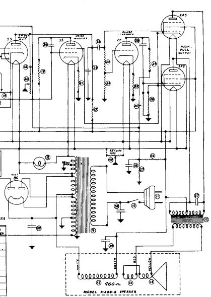
The next is a blow up of the speaker connections.
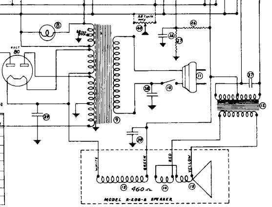
Examine your radio chassis, topside and underside. Where is the output transformer? Schematics will correctly indicate the radio's circuit but not necessarily the location. From the above section of the Rider's Schematic that I obtained from Nostalgia Air, it appears that the
output transformer should be on the chassis or on the underside of the chassis. You will need to inspect your radio chassis and speaker to locate the output transformer. It does not appear that the transformer is on the speaker based on your picture. The speaker looks like a period-correct speaker but may or may not be the original. Different manufacturers use different field coil impedances. Some put the whole radio B+ load through the field coil. Other do not put the output stage plate load through the field coil. Almost all "electrodynamic" speakers (speakers with an electromagnet instead of a permanent magnet field) have a "hum bucking" coil. this is wound along with the field coil and is wired in series with the voice coil with a polarity that should "buck" or cancel any hum not filtered out by the rest of the power supply design.
.
If the transformer is on the chassis (maybe the underside?), then there should be 4 leads to the speaker. 2 of these leads (white and green) are for the field coil. The other 2 red and yellow) are for the speaker voice coil. Between the rectifier filament (white wire) and the output tube screens (green wire) there should be about 460 Ohms. Between the speaker voice coil (and hum bucking coil in series with it) the resistance should be very low. Because the speaker voice coil / hum bucking coil is in parallel with output transformer secondary, the connection must be disconnected to correctly measure the voice coil.
If 2 of these speaker leads go directly to the output tube plate connections, then your speaker is likely incorrect as only "magnetic" speakers have a direct connection to the output stage without a transformer. In the 1930s, magnetic speakers were used only on battery powered radios.
Hope this helps.
"Do Justly, love Mercy and walk humbly with your God"- Micah 6:8
"Let us begin to do good"- St. Francis
Best Regards,
MrFixr55
Posts: 325
Threads: 34
Joined: Dec 2019
City: Elkhart
State, Province, Country: Indiana
Quote:Hi Cap'n Clock,
Unfortunately, I do not have this radio. This is a shame because this should be a good performer. 2A5s are the same as 42s (6F6s) except for filament voltages. at 7 watts audio and an 8" or 10" speaker, this set should have a big sound. I always recommend adding an aux input to radios like these so period music can be played from a computer or MP3 player with better fidelity than through an AM transmitter.
Attached below are sections of the schematic. The first one is the complete audio and power supply section.
[Image: https://philcoradio.com/phorum/attachment.php?aid=31256]
The next is a blow up of the speaker connections.
[Image: https://philcoradio.com/phorum/attachment.php?aid=31257]
Examine your radio chassis, topside and underside. Where is the output transformer? Schematics will correctly indicate the radio's circuit but not necessarily the location. From the above section of the Rider's Schematic that I obtained from Nostalgia Air, it appears that the
output transformer should be on the chassis or on the underside of the chassis. You will need to inspect your radio chassis and speaker to locate the output transformer. It does not appear that the transformer is on the speaker based on your picture. The speaker looks like a period-correct speaker but may or may not be the original. Different manufacturers use different field coil impedances. Some put the whole radio B+ load through the field coil. Other do not put the output stage plate load through the field coil. Almost all "electrodynamic" speakers (speakers with an electromagnet instead of a permanent magnet field) have a "hum bucking" coil. this is wound along with the field coil and is wired in series with the voice coil with a polarity that should "buck" or cancel any hum not filtered out by the rest of the power supply design.
.
If the transformer is on the chassis (maybe the underside?), then there should be 4 leads to the speaker. 2 of these leads (white and green) are for the field coil. The other 2 red and yellow) are for the speaker voice coil. Between the rectifier filament (white wire) and the output tube screens (green wire) there should be about 460 Ohms. Between the speaker voice coil (and hum bucking coil in series with it) the resistance should be very low. Because the speaker voice coil / hum bucking coil is in parallel with output transformer secondary, the connection must be disconnected to correctly measure the voice coil.
If 2 of these speaker leads go directly to the output tube plate connections, then your speaker is likely incorrect as only "magnetic" speakers have a direct connection to the output stage without a transformer. In the 1930s, magnetic speakers were used only on battery powered radios.
Hope this helps.
Yes that was very helpful, I had the original Rider's Book that had the service data but the schematic they had in there for this radio didn't have a very detailed drawing of the audio section of this radio, just an illustration in the schematic showing the various connections to the speaker but no labels showing what connections was what and where each connection went to.
The way the speaker that is in this radio was wired up is that there was a bare copper wire coming from the back of the speaker (I'm assuming that would of been the humbucking coil) that was covered with spaghetti tubing that one of the wires that looked like that was connected directly to the voice coil connection and the other one was connected to one of the wire leads coming out of the radio chassis (I'm not sure which color it was though because the wire insulation is so badly faded that the color is hard to make out) but the way it was connected didn't look quite right, and then one of the other wire leads coming out of the chassis for the speaker was connected to the other voice coil connection but no humbucking coil connection to the other voice coil connection. The other two wires coming from the chassis was going to the field coil, which didn't seem quite right, but I could be wrong which is why I wanted to see a well marked circuit diagram of the speaker connections to confirm whether or not it was wired up correctly or not.
Is it possible that if the previous owner of this radio (or one of the previous owners of this radio) did indeed replace the original speaker in this radio with an "aftermarket" speaker that they may have wired it up in a way that it would work with that particular speaker (which would of been a little different from how the original speaker would of been wired up) and that's why it looked off to me as far as how it was wired up? Because perhaps this speaker wasn't a true electrodynamic speaker but perhaps a modified PM speaker?
I'm asking because this speaker has no makers marks or any other identification marks on it except for a number that is rubber stamped in white ink on the speaker cone and that's it, no serial numbers, no model numbers, no brand name markings or anything, and the cover that goes over the field coil/Hum-bucking coil area doesn't look factory to me, it looks like it was added onto the speaker.
Posts: 325
Threads: 34
Joined: Dec 2019
City: Elkhart
State, Province, Country: Indiana
I have completely recapped this radio and am currently waiting for a replacement pilot light socket for the tuning dial, because the original dial light socket was broken at the socket itself. One question I have is about the rubber tire that is used with the tuning knob to rotate the tuning dial, mine is no longer capable of rotating the tuning dial anymore (it slips and has no grip anymore besides having a groove worn into it from the traction teeth on the tuning dial assembly, and I was wondering what would be a good substitute for the original rubber tire from the tuning knob? I was thinking of using a rubber grommet that was similar in size to the original rubber tire when it comes to the inner and outer diameter but I'm not sure if the groove cut into the grommet for allowing it to be mounted into a hole on a metal chassis would be able to grip the tuning dial assembly's traction teeth.
Posts: 1,256
Threads: 32
Joined: Jan 2014
City: Wellborn Florida
Try McMaster-Carr supply they have lots of stuff O rings and flat sheets and solid round tubing. If you had the plans for a star ship you could probably build warp drive engines and the rest of the ship. Just have to find a source for the dilithium crystals.
Posts: 325
Threads: 34
Joined: Dec 2019
City: Elkhart
State, Province, Country: Indiana
Thanks for the help, I was able to make an old wire grommet that was about the same size as the original rubber tire work by wrapping it in friction tape.
Now another question concerning the cabinet, it looks like the cabinet may have had some sort of toner lacquer finish on it at some point in time and from what I could see on some other cabinets of the same model where the finish on them was in better shape than on mine, seems to confirm that assumption.
What colors of toner lacquer should I use to restore the finish on this cabinet? I currently have in my possession Van Dyke Brown and another color of Toner Lacquer I can't remember the name of.
the shade of Lacquer Toner used on this cabinet looks like a darker shade of brown or maybe almost a blackish color and it appears it was used on the base trim and on the top and sides and the knobs looked to a light brown color Toner Lacquer used on it and the lighter parts of the cabinet were just natural wood stain.
Posts: 325
Threads: 34
Joined: Dec 2019
City: Elkhart
State, Province, Country: Indiana
OK, so I have run into a little issue with my radio, I put the radio back together and turned it on and I can't get the radio to pull in any stations.
I had to remove the tuning capacitor from the radio in order to replace the old dry-rotted rubber grommets that served as spacers between the chassis and the tuning capacitor and when I did that I had to unsolder a couple of wires from the bottom of the tuning capacitor and I made sure to resolder the wires back where they came from.
I'm assuming the radio may be in need of a realignment since I had to remove the tuning capacitor from the radio, but the problem is that the radio uses an odd-ball IF Frequency of 177.5 kHz which none of my signal generators I own are capable of going down that far, as the lowest they can go is 300 kHz on one (a late 1940s Signal Generator made by a company up in New York State) and 440 kHz on the other, (a 1970s vintage Hewlett Packard Signal Generator) and I was wondering if there's a way to make a signal generator that doesn't go down to 177.5 kHz do a harmonic of 177.5 kHz that the radio can pick up on and align the IF to and still allow the radio to function properly as if it were aligned to 177.5 kHz? If so what's the frequency I need to use and are the alignment instructions the same otherwise?
Thanks for your help.
-Levi
Posts: 863
Threads: 50
Joined: Feb 2013
City: Shenandoah,
State, Province, Country: Pennsylvania
Levi, you might be able to temporarily tack a small cap in parallel to the tuning capacitor to bring down the frequency to 177.5 KC. You would need to experiment with different values and a frequency counter would be a big help in determining what frequency you are producing! Hope this helps!
Ron
Bendix 0626. RCA 8BX5. RCA T64
Philco 41-250. Philco49-500
GE 201. Philco 39-25
Motorola 61X13. Philco 46-42 Crosley 52TQ
Philco 37-116. Philco 70
AK 35 Philco 46-350
Philco 620B. Zenith Transoceanic B-600
Philco 60B. Majestic 50
Philco 52-944. AK 84
Users browsing this thread: 2 Guest(s)
|
|
Recent Posts
|
|
Philco 610B oscillator wiring
|
| Some info from Beitmans says late production. David David — 06:06 PM |
|
Restoring Philco 96
|
| Oh wow! Just found this thread. Brings me back to early days on this phorum. I did a 96 back in 2017. Thread here:
...rfeenstra — 06:05 PM |
|
Philco 610B oscillator wiring
|
| Thanks for the replies. It's not the really the hum that I am after. Just trying to understand why only the shortwave ba...Tubester — 04:01 PM |
|
Restoring Philco 96
|
| 70 and 90 are Superhets, but at least the 2x45 model of 90 uses the Plate detector (and so does 70).
Also the Atwaters,...morzh — 03:28 PM |
|
Restoring Philco 96
|
| Morzh, Prayers for your mom. I am sure that there was enough pain living through the Holocaust as a child. I pray dail...MrFixr55 — 02:19 PM |
|
Philco 610B oscillator wiring
|
| Hi Dan,
Divide and conquer. First off trry to differentiate between 60Hz and 120 Hz hum. 120 Hz hum has a higher pit...MrFixr55 — 01:49 PM |
|
Restoring Philco 96
|
| Yes, other than takin a toll on your back, they are undeed way more repair friendly than many other Philcos.
To me, som...morzh — 01:04 PM |
|
Philco 610B oscillator wiring
|
| If the wires look like they were this way from the factory (very neat and very dull soldering joints), I'd leave them be...morzh — 12:58 PM |
|
My Philco 37-116 Restore
|
| I managed to open up the Expander Unit and replace the grid cap wires. Tested the connections found they looked good and...dconant — 12:19 PM |
|
610B Oscillator Questions
|
|
I've included a picture of the 'actual' schematic I created. I double checked several times and it appears to be accur...Tubester — 09:26 AM |
|
Who's Online
|
There are currently 2831 online users. [Complete List]
» 4 Member(s) | 2827 Guest(s)
|
|
|

|
 
|


![[-] [-]](https://philcoradio.com/phorum/images/bootbb/collapse.png)


