Posts: 9
Threads: 2
Joined: Jun 2024
City: Lake Jackson
State, Province, Country: Texas
Is there a best way to use the single-screw terminal on the back of this 1950 Philco? (best antenna type, possible grounding needs, etc.). I have restored and aligned it, and works great with the loop. Any input is very appreciated.
Mark
Posts: 256
Threads: 15
Joined: Jan 2024
City: Tulsa
State, Province, Country: Oklahoma
Good afternoon! Could you possibly attach a photo to show us the connector? Could you also verify the model number? 123 doesn’t sound right. It’ll probably be 50-xxx.
Joseph
Philco 46-480
Philco 49-906
(This post was last modified: 12-30-2024, 06:11 PM by
jrblasde.)
Posts: 1,256
Threads: 32
Joined: Jan 2014
City: Wellborn Florida
Not a Philco but common during that time frame page 2 ant hookup. David
https://philcoradio.com/phorum/showthrea...7#pid90017
Posts: 1,119
Threads: 44
Joined: Feb 2015
City: Roseville, MN
Posts: 9
Threads: 2
Joined: Jun 2024
City: Lake Jackson
State, Province, Country: Texas
Thanks all. Sorry about the model #. It is a 50-922, and yes, run # 123.
Posts: 9
Threads: 2
Joined: Jun 2024
City: Lake Jackson
State, Province, Country: Texas
Not sure how to post a picture on this site. Any advice?
Posts: 9
Threads: 2
Joined: Jun 2024
City: Lake Jackson
State, Province, Country: Texas
the lead for the screw terminal connects with one of the leads going directly to the internal loop antenna. Once I find out how to post a pic, I will. Many thanks....and Happy New Year everyone.
Posts: 256
Threads: 15
Joined: Jan 2024
City: Tulsa
State, Province, Country: Oklahoma
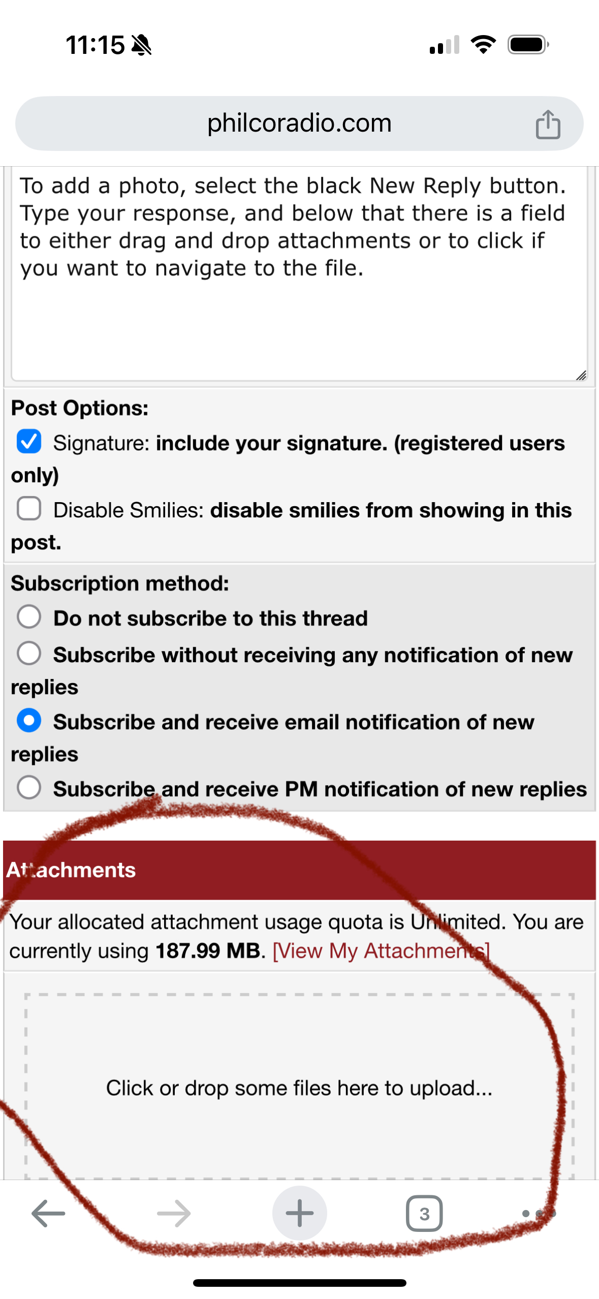
To add a photo, select the black New Reply button. Type your response, and below that there is a field to either drag and drop attachments or to click if you want to navigate to the file.

Joseph
Philco 46-480
Philco 49-906
Posts: 1,256
Threads: 32
Joined: Jan 2014
City: Wellborn Florida
Some info from Beitmans.

Posts: 9
Threads: 2
Joined: Jun 2024
City: Lake Jackson
State, Province, Country: Texas
Posts: 9
Threads: 2
Joined: Jun 2024
City: Lake Jackson
State, Province, Country: Texas
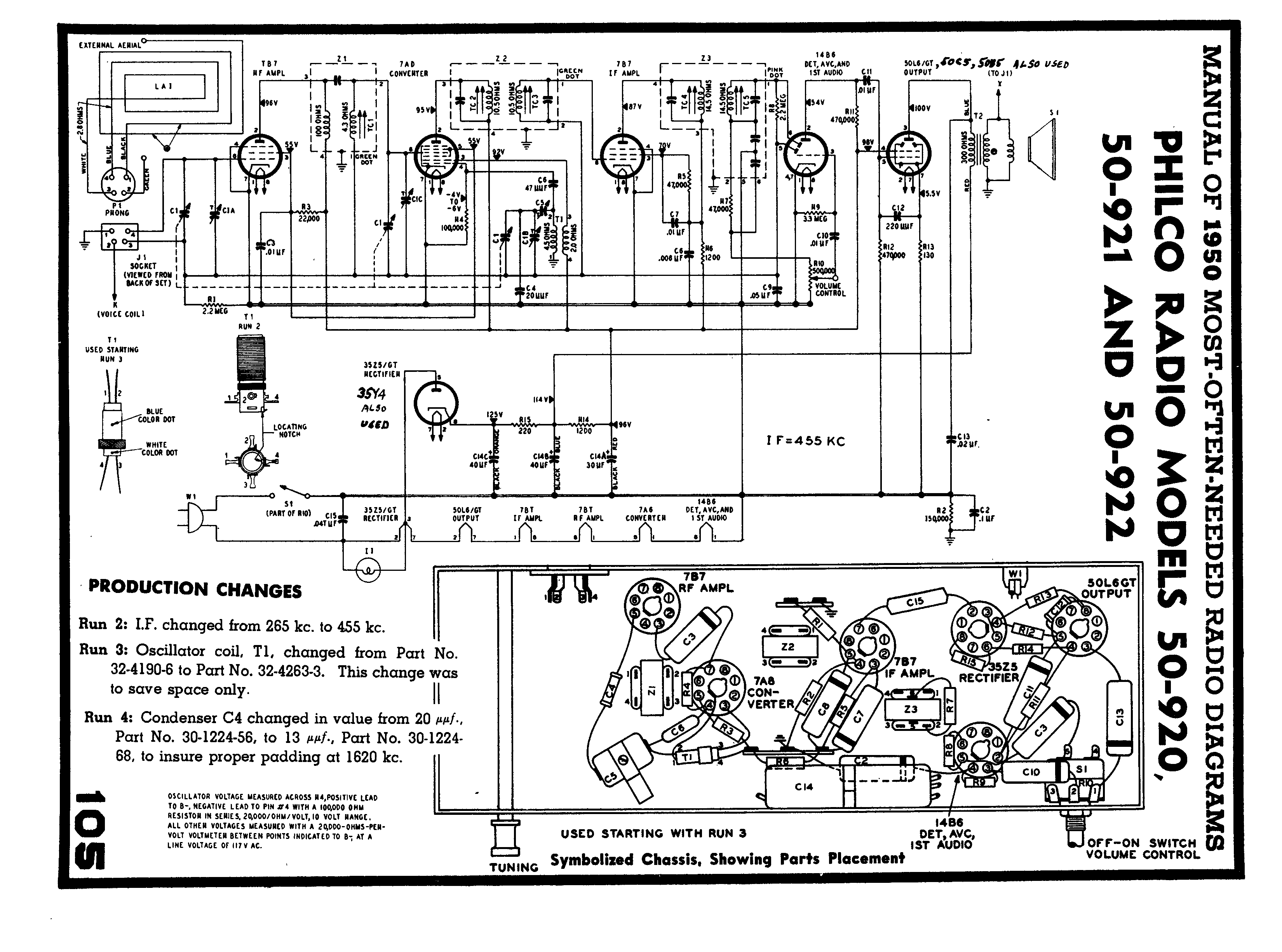
Thanks everyone. hope the pics work. and thanks for the schematic. Mine has the 50C5 aud. output and 35Y4 rect.
Posts: 9
Threads: 2
Joined: Jun 2024
City: Lake Jackson
State, Province, Country: Texas
I have tried only a long wire on the external terminal. Get some overloading on strong stations actually using the wire, but weak ones are strengthened. This is during the daytime.
Mark
Posts: 1,119
Threads: 44
Joined: Feb 2015
City: Roseville, MN
Your antenna is working as intended. The loop antenna is an rf transformer with the connection available for an external wire antenna. The signal on that wire brings in a stronger signal resulting in more gain to the radio.


![[-] [-]](https://philcoradio.com/phorum/images/bootbb/collapse.png)


